
Fixing method and fixing structure of optical lens in laser system

An optical lens and fixing method technology, applied in laser parts, laser parts, lasers, etc., can solve problems such as damage to optical lenses, contamination of lens surfaces, lens loosening, etc., to improve firmness, increase friction, and ensure The effect of laser performance

Inactive Publication Date: 2020-01-10
AVIC BEIJING AERONAUTICAL MFG TECH RES INST
View PDF9 Cites 0 Cited by
  • Summary
  • Abstract
  • Description
  • Claims
  • Application Information

AI Technical Summary

Problems solved by technology

[0006] The purpose of the present invention is to provide a fixing method and fixing structure for the internal optical lens of the laser system, to solve the problem of volatilization of the adhesive that occurs when the optical lens inside the laser system is fixed on the frame in the prior art, polluting the surface of the lens, and operating during operation. Improperly attaching excess adhesive to the clear surface of the lens, improper handling during the pressing operation leads to damage to the optical lens and easy loosening of the lens

Method used


Image

  • Fixing method and fixing structure of optical lens in laser system
  • Fixing method and fixing structure of optical lens in laser system
  • Fixing method and fixing structure of optical lens in laser system

Examples


Embodiment Construction

[0031] The specific implementation manners of the present invention will be further described in detail below in conjunction with the accompanying drawings and embodiments. The following examples are used to illustrate the present invention, but are not intended to limit the scope of the present invention.

[0032] In the description of the present invention, it should be understood that the terms "center", "longitudinal", "transverse", "upper", "lower", "front", "rear", "left", "right", "vertical The orientations or positional relationships indicated by "straight", "horizontal", "top", "bottom", "inner", "outer", etc. are based on the orientation or positional relationship shown in the drawings, and are only for the convenience of describing the present invention and simplifying the description , rather than indicating or implying that the device or element referred to must have a particular orientation, be constructed and operate in a particular orientation, and thus should ...


PUM


Abstract

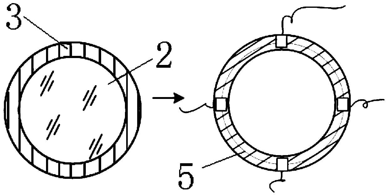
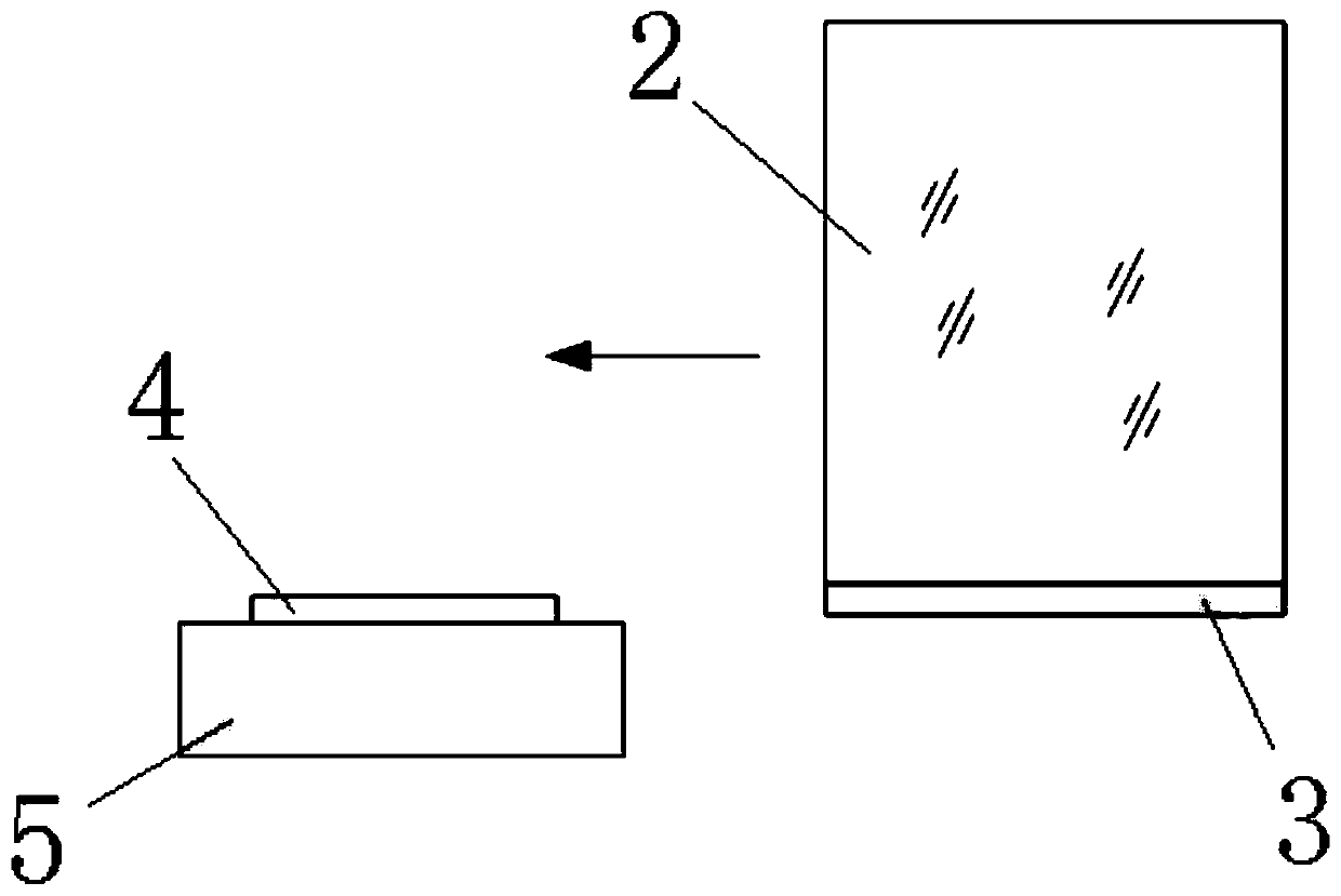
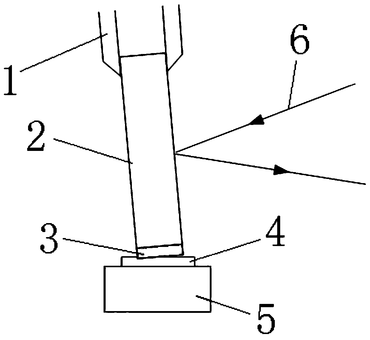
The invention discloses a fixing method and a fixing structure of an optical lens in a laser system. A lens frame and optical lenses are included, the optical lenses are installed on the lens frame, abonding pad is arranged between the lens frame and the optical lenses, and a metal layer is arranged at a position where the optical lenses and the bonding pad are contacted. A roughening treatment layer is arranged on a surface of the metal layer, and the metal layer can make contact with a welding flux in a larger area in a welding process so that firmness of the metal layer and the welding flux is improved. A welding mode is adopted to carry out fixation so that a problem of loosening of the optical lens relative to a threaded pressing mode can be avoided. Compared with an adhesive adoptedin the prior art, the welding flux does not volatilize so that a surface of the optical lens, a crystal surface and the like in a sealed laser cavity can be prevented from being polluted, laser performance is ensured, and meanwhile, the adhesive cannot be attached to a light-transmitting surface of the optical lens due to misoperation in an operation process.

Description

technical field [0001] The invention relates to a fixing method and structure of an optical lens, in particular to a fixing method and a fixing structure of an optical lens inside a laser system. Background technique [0002] Generally, a laser system contains multiple optical lenses, such as cavity mirrors, coupling lenses, reflectors, etc. Currently, each optical lens is usually fixed on the metal frame by means of gluing, screwing, etc. Among them, the way of gluing is to apply a layer of adhesive such as silicone rubber or ultraviolet photosensitive adhesive on the outer edge of the lens to bond the lens to the metal frame. When performing this operation, if the operation is improper, it is easy to attach excess adhesive to the light-transmitting surface of the lens, which will affect the use of the lens. In addition, silicone rubber and other adhesives are volatile, which will pollute the lens surface and crystal surface in the sealed laser cavity, seriously affecting ...

Claims


Application Information

Patent Timeline
Patent Type & Authority Applications(China)
IPC IPC(8): H01S3/02H01S5/022
CPCH01S3/02H01S5/02325
Inventor 崔丽郝赫张亦卓韩林森
Owner AVIC BEIJING AERONAUTICAL MFG TECH RES INST
Learn More