Multispectral transceiving integrated sensor and non-contact nondestructive glucometer
An integrated sensor, multi-spectral technology, applied in the field of blood glucose meters, can solve the problems of inability to medical data, use, and low measurement accuracy, and achieve the effects of reducing crosstalk noise, improving accuracy, and improving test accuracy
- Summary
- Abstract
- Description
- Claims
- Application Information
AI Technical Summary
Problems solved by technology
Method used
Image
Examples
Embodiment 1
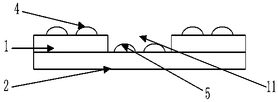
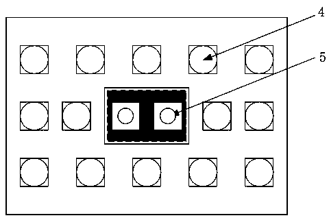
[0021] Such as Figures 1 to 5 A multi-spectral transceiver integrated sensor is shown, including a substrate, an emission module, a detection module and a readout circuit. The emission module, detection module and readout circuit are all placed on the substrate, and the substrate provides support, electrical connection and heat dissipation for it . The emission module includes a variety of light sources 4 with different wavelength ranges; the detection module includes a variety of detectors 5 that can respond to different wavelength ranges, and the wavelength ranges that the detectors respond to correspond to the wavelength ranges of the light sources.
[0022] Preferably, there are at least 3 light sources and at least 2 detectors.
[0023] The operating principle of the sensor in this embodiment is the same as that of the prior art, that is, the principle of infrared spectrum absorption. The light source produces light in different wavelength ranges, first detect the ligh...
Embodiment 2
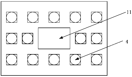
[0025] This embodiment is optimized on the basis of the structure of the above embodiment, that is, the substrate includes an upper substrate 1 and a lower substrate 2 overlappingly arranged, the upper substrate 1 is provided with a hole 11, and the transmitting module is placed on the upper substrate 1 , the detection module is placed on the lower substrate 2, that is, the emission module is closer to the target or object to be measured than the detection module; the detection module is placed at the position corresponding to the hole 11, and the upper substrate 1 is placed around the detection module. Blocking objects to avoid the impact of stray light on the detection module 2. The hole is preferably placed in the center of the upper substrate 1 .
Embodiment 3
[0027] This embodiment discloses a specific preferred method based on the structures of the foregoing embodiments. In this embodiment, 14 light sources and two detectors are used. The central wavelength of the light source is 525 nm, 525 nm, 700 nm, 700 nm, 880 nm, 880 nm, 940 nm, 940 nm, 950 nm, 950 nm, 1050 nm, 1050 nm, 1200 nm, 1200 nm, different The central wavelength corresponds to different wavelength ranges; the detector response wavelength ranges are 400 nm to 1000 nm and 1000 nm to 1700 nm respectively. Specifically, the light source can be light-emitting devices such as light-emitting diodes and laser diodes, and the detector can be photovoltaic detectors such as photodiodes and avalanche diodes or photoconductive detectors. The readout circuit is electrically connected with the detection module to realize the signal amplification of the detection module.
[0028] Specifically, its preparation process is as follows:
PUM
| Property | Measurement | Unit |
|---|---|---|
| wavelength | aaaaa | aaaaa |
Abstract
Description
Claims
Application Information
 - R&D
- Intellectual Property
- Life Sciences
- Materials
- Tech Scout
- Unparalleled Data Quality
- Higher Quality Content
- 60% Fewer Hallucinations
Browse by: Latest US Patents, China's latest patents, Technical Efficacy Thesaurus, Application Domain, Technology Topic, Popular Technical Reports.
© 2025 PatSnap. All rights reserved.Legal|Privacy policy|Modern Slavery Act Transparency Statement|Sitemap|About US| Contact US: help@patsnap.com


