
Threaded cylindrical pin fixed type automatic feeding and polishing device

An automatic feeding and polishing device technology, which is applied in the direction of grinding/polishing equipment, surface polishing machine tools, grinding feed movement, etc., can solve the problems of low work efficiency and inability to automatically load materials, so as to improve efficiency and improve Effect of Polishing Efficiency

Inactive Publication Date: 2020-01-14
长兴洪盛五金制品股份有限公司
View PDF1 Cites 6 Cited by
  • Summary
  • Abstract
  • Description
  • Claims
  • Application Information

AI Technical Summary

Problems solved by technology

[0004] The purpose of the present invention is to provide a threaded cylindrical pin fixed automatic feeding and polishing device to solve the problems in the above background that only a single threaded cylindrical pin can be processed at a time, and cannot be automatically loaded, and the work efficiency is low

Method used


Image

  • Threaded cylindrical pin fixed type automatic feeding and polishing device
  • Threaded cylindrical pin fixed type automatic feeding and polishing device
  • Threaded cylindrical pin fixed type automatic feeding and polishing device

Examples


Embodiment 1

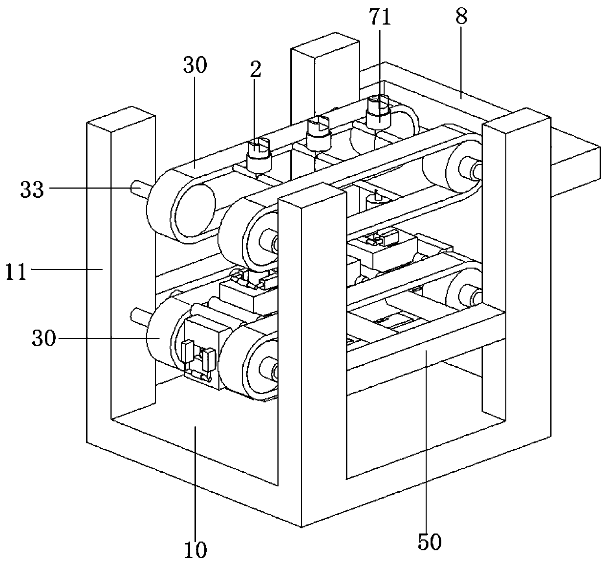
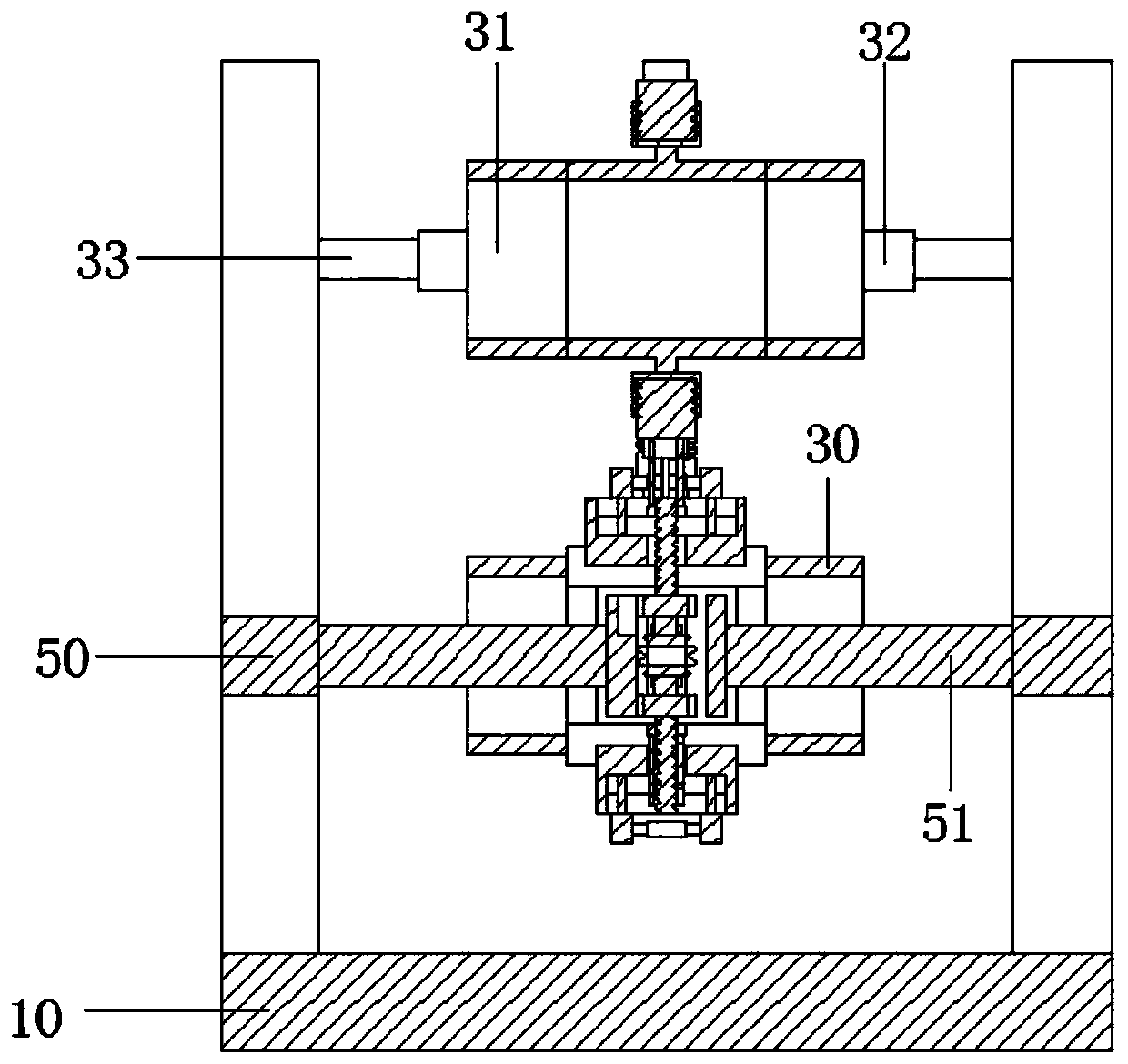
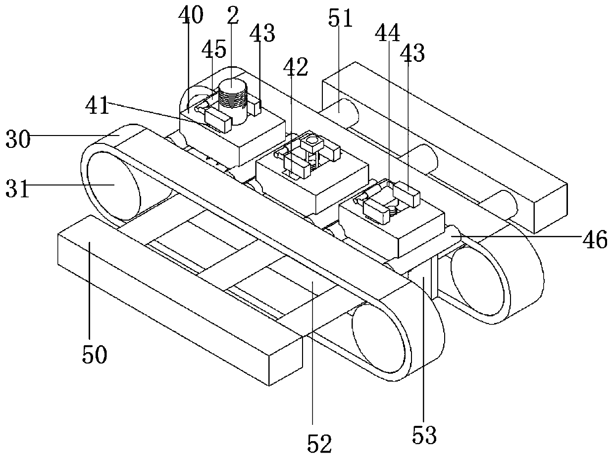
[0037] see Figure 1-11, the present invention provides a technical solution: a threaded cylindrical pin fixed automatic loading and polishing device, including a frame, a threaded cylindrical pin 2, a transmission part, an installation part, a power part, a transmission part, a fixed part and a polishing part 8, the frame It includes a base plate 10 and four sets of vertical plates 11. The vertical plates 11 are equidistant and symmetrically fixed on the four corners of the top of the base plate 10. The threaded cylindrical pin 2 includes a threaded part 20 and a smooth part 21. The center of the bottom end of the smooth part 21 is provided with a pin hole 22. , the transmission part includes two sets of double-cycle chains 30, the installation part includes a mounting plate 40 and two sets of connecting columns 46, the center of the bottom end of the mounting plate 40 is provided with a through groove 47, the horizontal section of the through groove 47 is a square, and the po...

Embodiment 2

[0044] see Figure 1-11 , wherein the same or corresponding components as those in Embodiment 1 use the corresponding reference numerals as those in Embodiment 1. For the sake of simplicity, only the differences from Embodiment 1 will be described below. The difference between the second embodiment and the first embodiment is that the bottom plate 10 is a counterweight bottom plate and the bottom is a friction surface, there are two sets of support plates 50 and they are symmetrically fixed between the vertical plates 11, and there are three sets of connecting rods 51 and Equidistantly arranged at the center of the side of the support plate 50 .

[0045] The working process of the present invention is: place the threaded cylindrical pin 2 to be polished on the installation part, and use the double-ended threaded telescopic rod 45 and the slider 42 to adjust the gap between the two sets of fixed splints 43 according to the diameter of the threaded cylindrical pin 2 The distanc...


PUM


Abstract

The invention discloses a threaded cylindrical pin fixed type automatic feeding and polishing device. The threaded cylindrical pin fixed type automatic feeding and polishing device comprises a frame,threaded cylindrical pins, a conveying part, mounting parts, a power part, transmission parts, fixing parts and a polishing part. The frame comprises a bottom plate and four sets of vertical plates. Each threaded cylindrical pin comprises a threaded part and a smooth part. Pin holes are formed in the centers of the bottom ends of the smooth parts. The conveying part comprises two sets of double-circulation chains. Each mounting part comprises a mounting plate and two sets of connecting posts. A through groove is formed in the center of the bottom end of each mounting plate. The horizontal cross section of each through groove is square. The power part comprises support plates, connecting rods, first toothed plates and second toothed plates. Tooth grooves are formed in the half parts of thefirst tooth plates. Racks are arranged on the half parts of the second tooth plates. Each transmission part comprises a vertical plate, a transverse plate, a transmission bearing, a stand column, a transmission gear, a screw sleeve, a jacking rod, a jacking block and a screw rod. Each fixing part comprises a T-shaped piece and a fixed screw cylinder. The polishing part is fixed between the two sets of vertical plates on one side.

Description

technical field [0001] The invention relates to the field of threaded cylindrical pin polishing, in particular to a threaded cylindrical pin fixed automatic feeding and polishing device. Background technique [0002] Threaded cylindrical pin is a kind of cylindrical pin, also known as slotted headless screw, which is fixed on the active part that needs to realize synchronous rotation by thread, and the exposed cylindrical part is connected in the pin hole of the driven part. It is used for positioning and connection. The optical axis is fixed in the pin hole by interference fit. During the production and processing of the threaded cylindrical pin, the smooth part needs to be polished. [0003] At present, the Chinese patent with the application number CN201821920767.6 discloses an auxiliary device for grinding the end face of a small-diameter cylindrical pin. It also has the function of polishing the end face of the cylindrical pin. It includes a cylindrical pin clamping m...

Claims


Application Information

Patent Timeline
IPC IPC(8): B24B41/00B24B7/16B24B29/02B24B41/06
CPCB24B7/16B24B29/02B24B41/005B24B41/067
Inventor 唐月盛朱国威
Owner 长兴洪盛五金制品股份有限公司
Features
  • Generate Ideas
  • Intellectual Property
  • Life Sciences
  • Materials
  • Tech Scout
  • Unparalleled Data Quality
  • Higher Quality Content
  • 60% Fewer Hallucinations
Learn More