Special flood preventing pump truck for transformer substation
A technology for substations and pump trucks, which is applied in the direction of freight vehicles, motor vehicles, and goods transport vehicles, etc. It can solve the problems of long distance of manual handling of flood control equipment, difficulty of manual handling, single drainage equipment, etc., to reduce operation and maintenance work time, improve drainage efficiency, and reduce labor intensity
- Summary
- Abstract
- Description
- Claims
- Application Information
AI Technical Summary
Problems solved by technology
Method used
Image
Examples
Embodiment 1
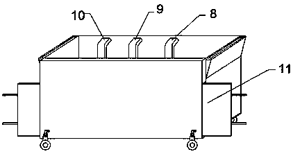
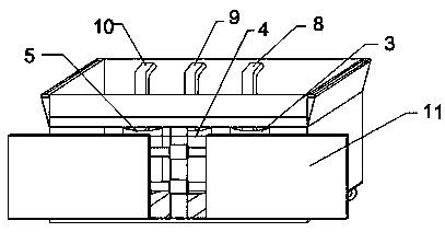
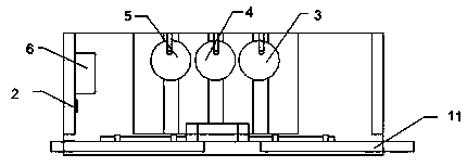
[0025] Embodiment 1: as figure 1 and 2 As shown, a special pump truck for flood control in a substation includes a car body 1, a roller is installed on the outer side of the lower part of the car body 1, and the roller is detachably connected to the car body 1 through a pin shaft, and the upper connection hole of the roller is connected to the outer side of the lower part of the car body through a pin shaft. , the lower part of the outer side of the car body is welded with a pin plate, the pin shaft is inserted into the pin plate to connect with the rollers, inserted into the bottom edge of the car body 1 and bonded with a rubber strip, when in use, after pushing the pump truck to the predetermined position, pull out the four A plug-in wheel makes the bottom surface of the pump truck contact the ground. At this time, the rubber strip bonded to the bottom edge of the trolley can just fill up the gap between the car body and the ground. A waterproof baffle 11 is movable installe...
Embodiment 2
[0030] Embodiment 2: as figure 1 As shown, the special pump truck for substation flood control has a plug-in waterproof board 12 installed on the outside of the waterproof baffle 11. The plug-in waterproof board is prefabricated and installed at the gate of the substation. When in use, the pump truck only needs to be pushed to the gate of the substation. , after adjusting the position of the pump truck to align with the plug-in waterproof board, slide the waterproof baffle out, the waterproof baffle is stretched out and connected with the corresponding plug-in waterproof board, and the waterproof baffle is plugged on the plug-in waterproof board and used The sealing strip seals and bonds the waterproof baffle and the plug-in waterproof board, which perfectly replaces the usual waterproof sandbags and saves handling work.
[0031] All the other structures are the same as in Example 1.
Embodiment 3
[0032] Embodiment 3: as Figure 6 and Figure 7 As shown, the car body 1 is equipped with a rack, and the waterproof baffle 11 is slidably set on the rack. The rack passes through the inside of the waterproof baffle. In the groove, a rotating handle is installed on the upper part of the car body, and the rotating handle is connected with the rotating gear through the rotating rod. The two sides of the rotating gear are respectively kneaded with two sets of sliding gears. , the sliding gear meshes with the rack. The operation and maintenance personnel manually turn the handle according to the needs to drive the rotating gear to rotate. The rotating gear drives the sliding gear to rotate. The stagnant water is effectively blocked.
[0033] All the other structures are the same as in Example 1.
PUM
 Abstract
Description
Claims
Application Information
 - R&D
- Intellectual Property
- Life Sciences
- Materials
- Tech Scout
- Unparalleled Data Quality
- Higher Quality Content
- 60% Fewer Hallucinations
Browse by: Latest US Patents, China's latest patents, Technical Efficacy Thesaurus, Application Domain, Technology Topic, Popular Technical Reports.
© 2025 PatSnap. All rights reserved.Legal|Privacy policy|Modern Slavery Act Transparency Statement|Sitemap|About US| Contact US: help@patsnap.com


