
Temperature regulation pre-treatment working system

A pretreatment and work-making technology, which is applied in the direction of steam engine devices, machines/engines, mechanical equipment, etc., to achieve the effect of creating economic benefits, energy saving and emission reduction economic benefits

Pending Publication Date: 2020-01-14
SHANGHAI KELAIPU ENERGY TECH CO LTD
View PDF5 Cites 0 Cited by
  • Summary
  • Abstract
  • Description
  • Claims
  • Application Information

AI Technical Summary

Problems solved by technology

However, this invention patent application cannot realize the power generation of the compression / expander through the heat generated by the hydrogen absorption and dehydrogenation of metal hydrogen storage materials.

Method used


Image

  • Temperature regulation pre-treatment working system
  • Temperature regulation pre-treatment working system
  • Temperature regulation pre-treatment working system

Examples


Embodiment 1

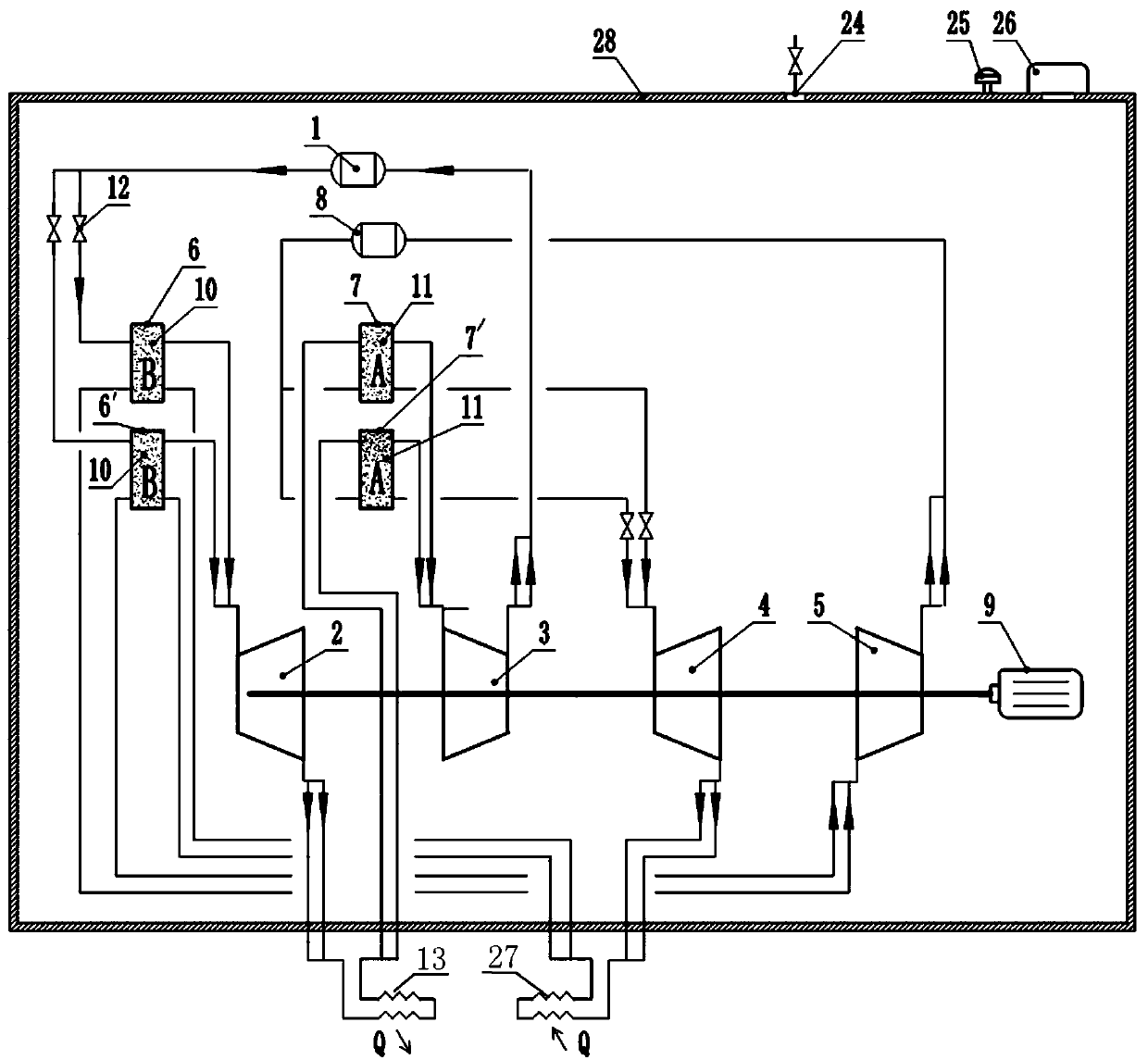
[0029] The invention provides a work system using a hydrogen reaction bed for temperature adjustment pretreatment, such as figure 1 As shown, the working system includes a high-pressure tank 1, a high-pressure expander 2, a high-pressure compressor 3, a low-pressure expander 4, a low-pressure compressor 5, No. 1 temperature changer 6, No. 2 temperature changer 7, and No. 3 temperature changer 6', No. 4 temperature changer 7', low pressure tank 8 and generator 9.

[0030] Specifically, No. 1 temperature changer 6, No. 2 temperature changer 7, No. 3 temperature changer 6' and No. 4 temperature changer 7' are respectively provided with a hydrogen absorption inlet, a hydrogen absorption outlet, a hydrogen discharge inlet and a hydrogen discharge outlet.

[0031] The outlet of high-pressure tank 1 is connected to the hydrogen suction inlet of No. 1 temperature changer 6 and No. 3 temperature changer 6' through valve 12, and the hydrogen suction outlet of No. 1 temperature changer 6...

Embodiment 2

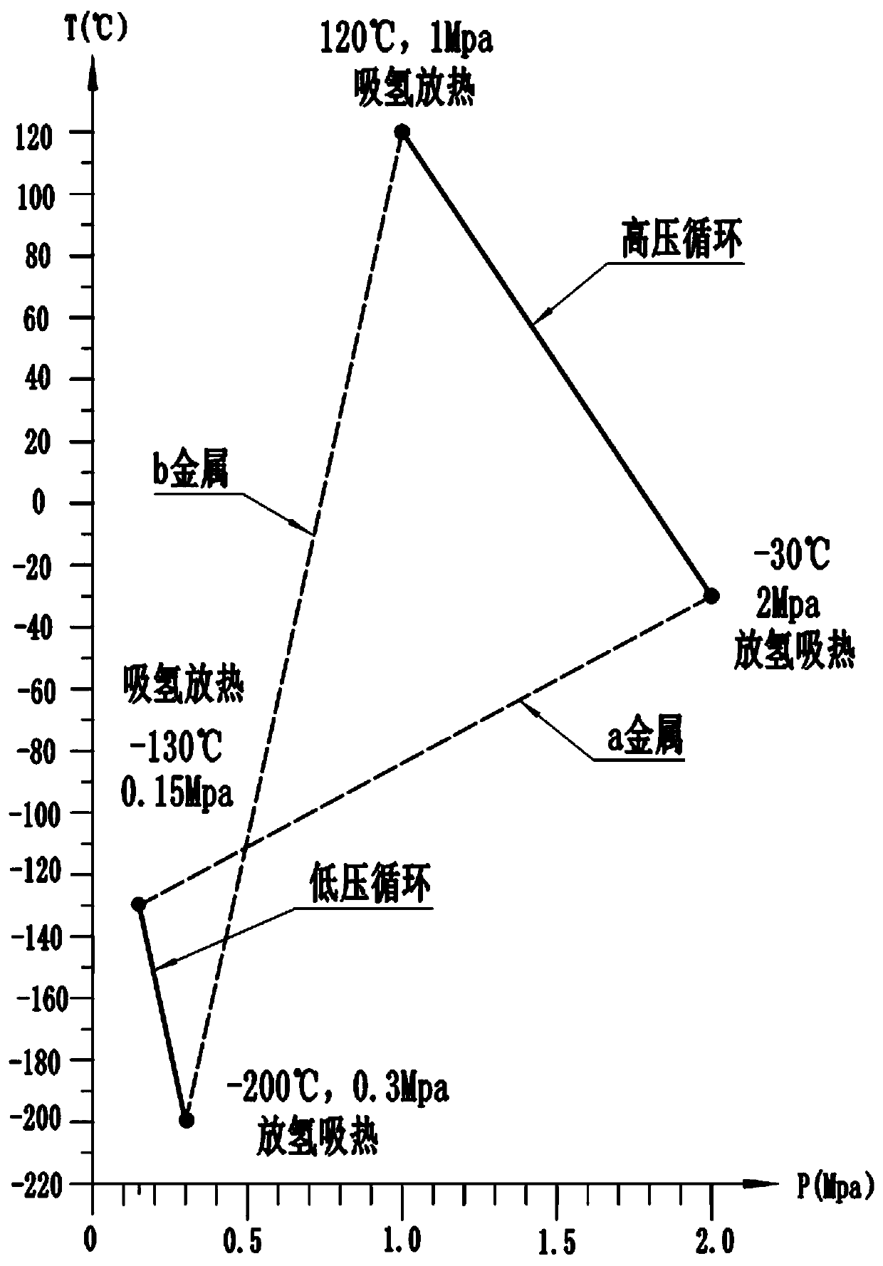
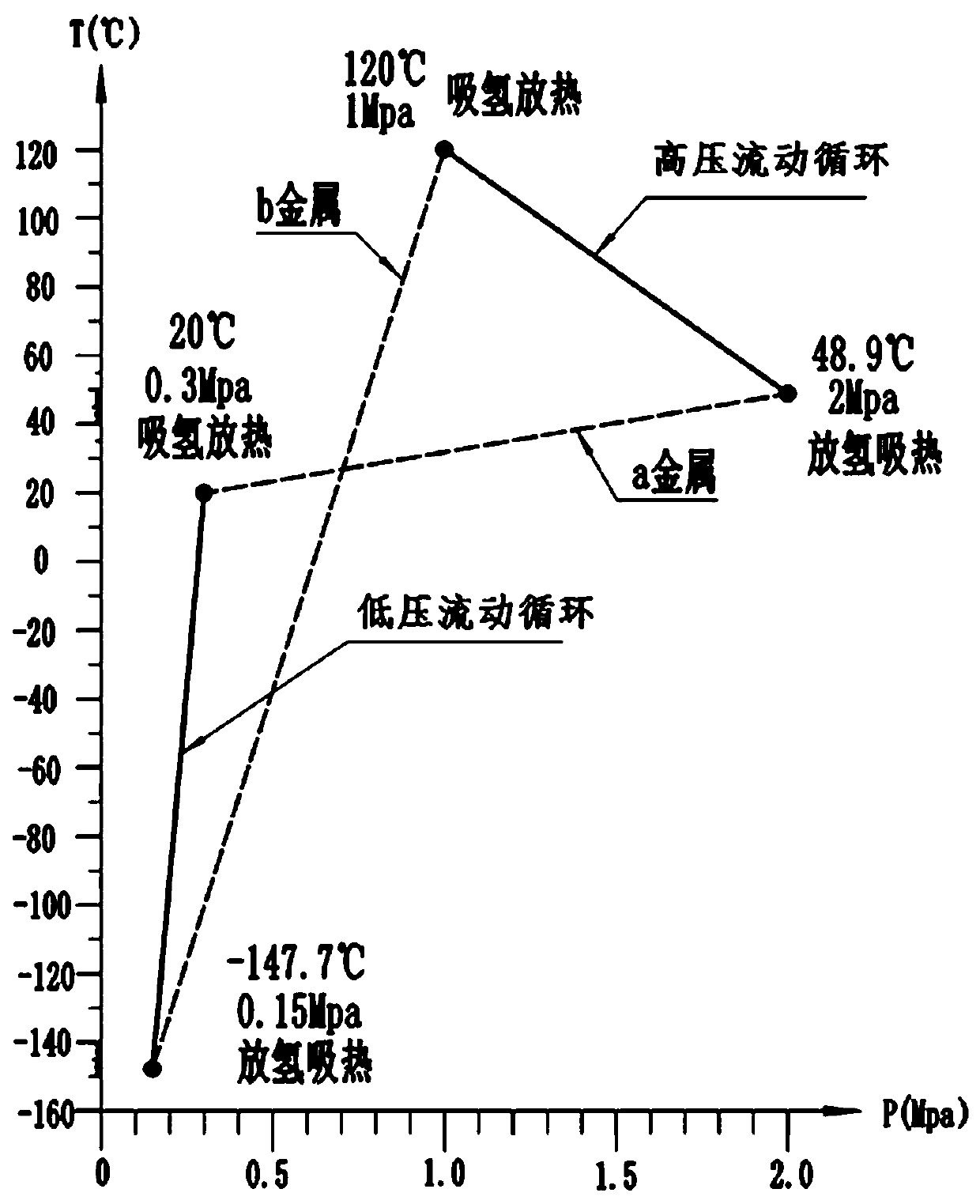
[0055] The working process of this embodiment is completely the same as that of Embodiment 1, the difference is that the working parameters of the system are adjusted. Among them, the B metal hydrogen storage material absorbs hydrogen and releases heat at temperatures below 120°C and above 1 MPa, and releases and absorbs heat at temperatures above -147.7°C and below 0.15 MPa. A metal hydrogen storage material releases hydrogen and absorbs heat above 48.9°C and below 2MPa, and absorbs hydrogen and releases heat below 20°C and above 0.3MPa. The four state points are as follows: image 3 shown.

[0056] In this embodiment, the specific process of a time sequence when the power system is working is: 2MPa at the outlet of the high-pressure tank 1, the high-pressure hydrogen at 34°C first enters the No. 1 temperature converter 6, and the B metal hydrogen storage material absorption part in the No. 1 temperature converter 6 Hydrogen releases a large amount of heat to raise the tempe...


PUM


Abstract

The invention relates to a temperature regulation pre-treatment working system. The system comprises a high-pressure tank, a high-pressure expander, a high-pressure compressor, a low-pressure expander, a low-pressure compressor, a heat transformer I, a heat transformer II, a heat transformer III, a heat transformer IV and a low-pressure tank; the high-pressure tank is sequentially connected to theheat transformer I, the high-pressure expander, the heat transformer II and the high-pressure compressor to form a high-pressure cycle; and the low-pressure tank is sequentially connected to the heattransformer IV, the low-pressure expander, the heat transformer III and the low-pressure compressor to form a low-pressure cycle. The system has the advantages that the compressors / expanders work todrive working equipment to work or drive power generation equipment to generate electricity.

Description

technical field [0001] The invention belongs to the technical field of energy comprehensive utilization, and relates to a work system for temperature regulation and pretreatment. Background technique [0002] The natural world is full of unlimited energy at normal temperature, such as air and sea water, which have potential for development. Most of the energy on the earth comes from the sun. In today's increasingly scarce energy sources, new renewable, green and clean power generation technologies are increasingly valued. Among new energy sources, hydropower and wind power generation technologies are widely used and the technologies are relatively mature. The development potential of hydropower is not great, and the wind power is too scattered, so it can only be applied in some specific areas, and the hydropower and wind power generation devices require a lot of investment and occupy a large area. Air energy has gradually entered people's field of vision. At present, air e...

Claims


Application Information

Patent Timeline
Patent Type & Authority Applications(China)
IPC IPC(8): F01K25/08F01K7/02F01K13/00F01K21/00
CPCF01K25/08F01K13/00F01K21/00F01K7/02
Inventor 贾鹏
Owner SHANGHAI KELAIPU ENERGY TECH CO LTD
Learn More