Accelerator pedal sensor dual signal output sensing circuit and its signal output control method

A technology of accelerator pedal and induction circuit, which is applied in the direction of engine control, circuit or fluid pipeline, power plant control mechanism layout, etc., can solve the problems of irrepression, high production cost, sensor failure, etc., and achieves a simple and ingenious circuit design. , The effect of reducing product cost and ingenious design method

Active Publication Date: 2022-03-01
扬州东博电子科技有限公司
View PDF5 Cites 0 Cited by
  • Summary
  • Abstract
  • Description
  • Claims
  • Application Information

AI Technical Summary

Problems solved by technology

The traditional circuit design has the following disadvantages: 1. The Hall chip is relatively "delicate", and the input voltage higher than the withstand voltage value of the chip will make it invalid. This circuit design increases the probability of circuit failure. Any failure of any output circuit of the output circuit will cause the sensor to fail; 2. The circuit design has no overvoltage protection function, which cannot suppress the voltage higher than 5V, and the Hall chip is easy to be damaged; 3. The circuit requires two Hall chips. The chip price is high and the production cost is high

Method used


Image

  • Accelerator pedal sensor dual signal output sensing circuit and its signal output control method
  • Accelerator pedal sensor dual signal output sensing circuit and its signal output control method
  • Accelerator pedal sensor dual signal output sensing circuit and its signal output control method

Examples


Embodiment 1

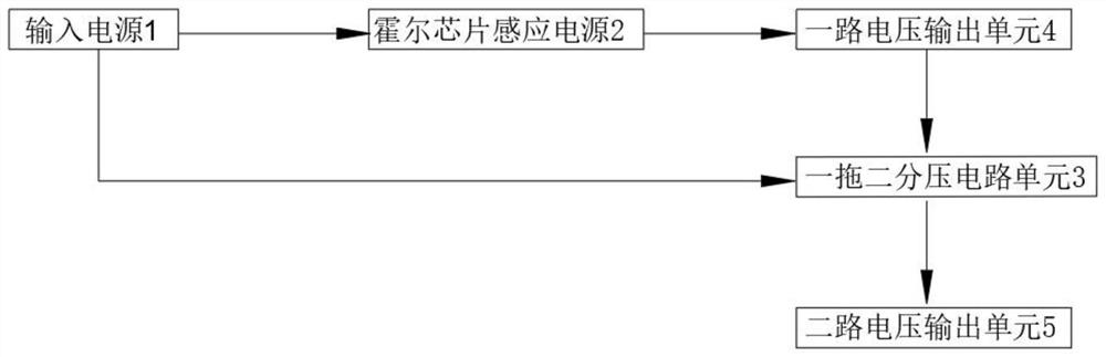
[0051] As attached in the manual figure 2 As shown, this embodiment includes an input power supply 1, and also includes a Hall chip induction unit 2, a one-to-two voltage divider circuit unit 3, one voltage output unit 4, and two voltage output units 5; the input power supply 1 is a Hall chip induction unit Unit 2, one-to-two voltage divider circuit unit 3 provides working power; Hall chip sensing unit 2 outputs corresponding electrical signals through one voltage output unit 4 according to the stroke of the accelerator pedal; one-to-two voltage divider circuit through one-to-two voltage output unit 4 The unit 3 divides the output electric signal according to the set ratio and outputs it through the two-way voltage output unit 5 .

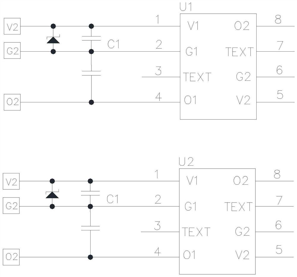
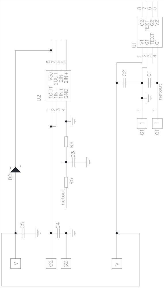
[0052] As attached in the manual image 3 As shown, the Hall chip sensing unit 2 includes a Hall chip U1, a capacitor C2, and a capacitor C1. The V1 terminal of the Hall chip is connected to the input power supply 1, and the capacitor C2 is conne...

Embodiment 2

[0058] In this embodiment, on the basis of Embodiment 1, the voltage follower is provided with working power by the input power supply 1, and a Schott for anti-reverse connection protection is provided between its Vcc input terminal and the input power supply 1. Substrate D2. The anode of the Schottky tube D2 is electrically connected to the input power supply, and the cathode is electrically connected to the Vcc terminal of the general-purpose operational amplifier.

Embodiment 3

[0060] This embodiment includes an input power supply 1, and also includes a Hall chip sensing unit 2, a one-to-two voltage divider circuit unit 3, one voltage output unit 4, and two voltage output units 5; the input power supply 1 is a Hall chip sensing unit 2, The one-to-two voltage divider circuit unit 3 provides working power; the Hall chip sensing unit 2 outputs corresponding electrical signals through one voltage output unit 4 according to the stroke of the accelerator pedal; the one-to-two voltage divider circuit unit 3 outputs the corresponding electrical signal The output electric signal is divided according to the set ratio and then output through the two-way voltage output unit 5 . This embodiment also includes a Hall chip overvoltage protection module 6, the Hall chip overvoltage protection module 6 includes a sampling output unit 7, a MOS tube logic control circuit unit 8; the input terminal of the MOS tube logic control circuit unit 8 and the sampling output unit ...


PUM


Abstract

The invention discloses a dual-signal output sensing circuit of an accelerator pedal sensor and a signal output control method thereof, belonging to the technical field of auto parts, and solving the problems of unreasonable design, high failure rate and high cost of the traditional sensor dual-signal output sensing circuit. It mainly includes Hall chip sensing unit, one-to-two voltage divider circuit unit, one-way voltage output unit and two-way voltage output unit. The invention has extremely low failure rate and long service life, breaks the inertial design thinking of the accelerator pedal sensing circuit, and has extremely important significance in the technical field of sensor circuits and in the technical field of accelerator pedals.

Description

technical field [0001] The invention belongs to the technical field of auto parts, and in particular relates to an accelerator pedal sensor dual-signal output sensing circuit and its signal, which output two-way signals from one chip, effectively reduce production costs, and have a very low failure rate in circuit design. Output control method. Background technique [0002] At present, the type of sensor widely used on the accelerator pedal is a non-contact dual-signal output angular displacement sensor, and the design requires two voltage output signals. The traditional sensor dual signal output sensing circuit is shown in the attached drawing of the manual figure 1 As shown, the two outputs need two Hall chips, and the two outputs are output by two independent circuits. The traditional circuit design has the following disadvantages: 1. The Hall chip is relatively "delicate", and the input voltage higher than the withstand voltage value of the chip will make it invalid. T...

Claims


Application Information

Patent Timeline
Patent Type & Authority Patents(China)
IPC IPC(8): F02D11/10B60K26/02B60R16/02G01B7/30H03K17/687
CPCF02D11/10F02D11/106B60R16/02B60K26/02H03K17/687G01B7/30
Inventor 蒋永玉李功杰薛龙
Owner 扬州东博电子科技有限公司
Why Eureka
Try Eureka