Water wheel device and ship including same

A water wheel and impeller technology, which is applied in the field of water wheel devices and ships with water wheel devices, can solve the problems of inability to use ocean current energy to generate electricity, affecting the generation and efficiency of electric energy, and too many transmission devices, so as to achieve embedded Simple and practical structure, convenient maintenance and replacement, and the effect of reducing pollution

Active Publication Date: 2020-01-14
HARBIN ENG UNIV
View PDF11 Cites 8 Cited by
  • Summary
  • Abstract
  • Description
  • Claims
  • Application Information

AI Technical Summary

Problems solved by technology

Although this utility model patent can use the flowing kinetic energy of the water body to generate electricity, it will generate certain resistance to the navigation of the ship, and because the hydroelectric power generation device is installed in the closed device, the flow of water flow is blocked, so it cannot make good use of ocean current energy to generate electricity
For the patent application number 201721457564.3, the name is the utility model patent of the marine direct flushing water turbine. There are power generation devices on both sides of the hull, and the generator is connected to the water turbine through multiple transmission devices. Due to too many transmission devices, it will cause a certain amount of energy loss. , and the water turbine will create resistance to the ship's navigation
For the patent application number 201620411895.2, the utility model patent named marine current power generation device, the device uses an underwater generator to generate electricity under the floating board floating on the sea surface. Since the device has no fixed device, the device will shake with the current. Affects electricity generation and efficiency
To sum up, the patents of the existing hydroelectric generating sets installed on ships are all insufficient, and they only have the function of generating electricity. How to efficiently use this additional device under the existing ship conditions to produce more beneficial effects, And it will not affect the normal navigation of the ship, the letter is to be resolved

Method used


Image

  • Water wheel device and ship including same
  • Water wheel device and ship including same
  • Water wheel device and ship including same

Examples


Embodiment 1

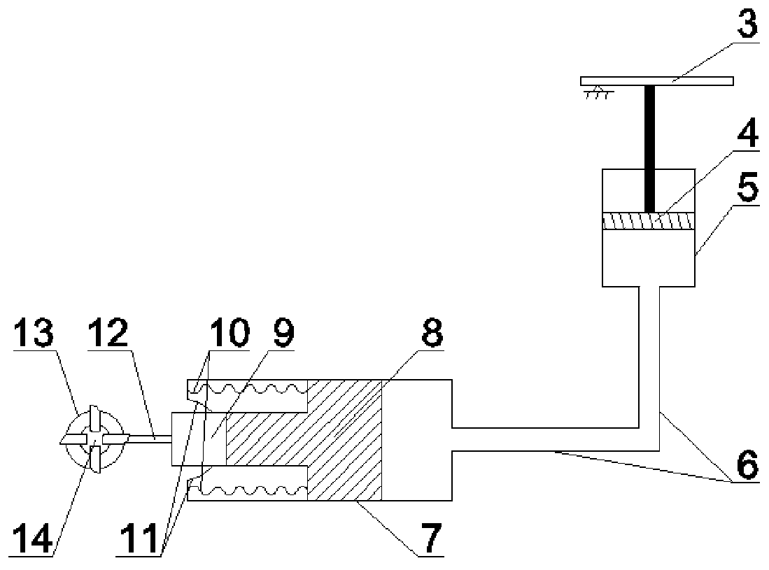
[0029] Such as figure 2 Shown is the concrete structure of a kind of water wheel device 23. Including the first impeller 14 and the first permanent magnet motor 13, the first impeller is connected with the first permanent magnet motor, and also includes the first hydraulic expansion device; the first hydraulic expansion device includes the first cylinder body 5 and the second cylinder body 7; the head end of the first cylinder and the tail end of the second cylinder are connected by a first pipeline, a first piston 4 is provided in the first cylinder, and a piston 4 is provided in the second cylinder The second piston 8; the first piston 4 is connected with the pushing device; the second piston is connected with the head end of the second cylinder through a spring; a stepping motor 9 is installed on the second piston; The stepping motor 9 is connected with the first permanent magnet motor 13; the stepping motor 9 is connected with the wall of the second cylinder through a so...

Embodiment 2

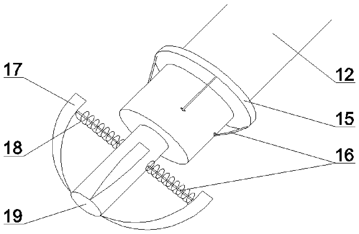
[0038] In order to facilitate maintenance and replacement of the water wheel device 23, the casing of the stepper motor 9 and the first permanent magnet motor 13 in Embodiment 1 are fixed by an embedded structure. Such as image 3 , Figure 4 and Figure 5 As shown, there are first discs 15 on the first rotating shaft 12 that can slide along both sides of the rotating shaft, and the top end of the first rotating shaft 12 is connected to the tail end of the second rotating shaft 19 . There are 4 blades 17 in total, which play a fixing role, and one end thereof is connected with the top of the second rotating shaft 19 , and the other end is connected with the second rotating shaft 19 through the second spring device 18 . There is a rope 16 at the middle position inside the second spring device 18, and one end of the rope 16 is fixed on the blade 17, and the other end passes through the inside of the second rotating shaft 19 and the first rotating shaft 12, and passes out from ...

Embodiment 3

[0040] Such as Figure 9 As shown, it is another water wheel device. In order to improve the power generation efficiency, a double water turbine structure is adopted, including the water wheel device 23 and the second water wheel power generation device 22 in Embodiment 1. The second hydroelectric generating device 22 includes a second impeller and a third hydraulic expansion device 27; the third hydraulic expansion device includes a fifth cylinder and a sixth cylinder; the tail end of the sixth cylinder passes through the first The four pipelines are connected to the first pipeline; the fifth cylinder is connected to the third pipeline; the third pipeline passes through the first pipeline and the fourth pipeline; the fifth piston is arranged in the third pipeline ; The upper part and the lower part of the fifth piston are respectively provided with circular hole passages, the upper end of the fifth piston is connected with the push device, and the lower end of the fifth pisto...


PUM


Abstract

The invention belongs to the technical field of water wheel motors, and particularly relates to a water wheel device and a ship including the same. According to the water wheel device with multiple functions suitable for the ship, power generation is carried out by utilizing tidal current energy, the functions of propulsion and anti-rolling are realized, the pollution of the ship to the marine environment is reduced, the endurance of the ship is improved, the navigation speed of the ship is increased, and the stability of the ship is enhanced. According to the water wheel device and the ship including the same, a hydraulic expansion and retraction device controls the expansion and retraction of the water wheel device, and the water wheel device is capable of extending out of the ship bodywhen the water wheel device is used and retracting into the ship body when the water wheel device is not used, so that the normal navigation of the ship is not affected by the water wheel device, andthe embedded structure of the water wheel device is simple and practical and convenient to maintain and replace. According to the water wheel device and the ship including the same, the water wheel device is efficiently utilized under the existing ship condition, the functions of power generation, propulsion and anti-rolling are integrated, and the use of the inner space of the ship body is reduced.

Description

technical field [0001] The invention belongs to the technical field of water wheel motors, and in particular relates to a water wheel device and a ship with the water wheel device. Background technique [0002] Due to the huge energy consumption of ships, and the vast majority of ships use diesel engines as power devices, this will inevitably consume a large amount of non-renewable energy, thereby polluting the environment. Moreover, the marine environment is varied, and the wind and waves will cause certain sway to the ship. Therefore, the patent of the present invention designs a hydroelectric generating set with multiple functions such as power generation, propulsion and anti-rolling, which can reduce the consumption of non-renewable energy and environmental pollution on the one hand, improve the endurance of the ship, and speed up the speed on the other hand. Increase ship speed and reduce ship swing, improve ship stability. [0003] For the patent application number 2...

Claims


Application Information

Patent Timeline
Patent Type & Authority Applications(China)
IPC IPC(8): F03B13/26F03B11/00B63H5/08B63H5/125B63B39/08
CPCB63B39/08B63H5/08B63H5/125F03B11/00F03B13/264F05B2220/7068F05B2240/931Y02E10/20Y02E10/30
Inventor 程鹏史超李睿烨李伟力梁宁李攀龙王晓超成倩
Owner HARBIN ENG UNIV
Why Eureka
Try Eureka