Dynamic load shear test device and method for emergency disconnection self-sealing structure

A technology of a test device and a test method, which is applied in the field of dynamic load shear test device, can solve the limitation of difficult load action time and clamp speed change, cannot accurately reflect the force condition and damage state, and there is no dynamic load shear test research. Related public reports and other issues, to achieve the effect of simple test steps, perfect test plan, convenient radial shear load range

Active Publication Date: 2020-01-14
NANJING UNIV OF AERONAUTICS & ASTRONAUTICS
View PDF24 Cites 1 Cited by
  • Summary
  • Abstract
  • Description
  • Claims
  • Application Information

AI Technical Summary

Problems solved by technology

[0003] At present, domestic research on emergency disconnection self-sealing structures is still in its infancy, and there is no relevant public report on its dynamic load shear test research
At the same time, most of the devices and methods for dynamic load tests at this stage focus on tensile dynamic load tests, and leverage loading-load amplification mechanisms are often used to convert impact loads into required test loads. The complexity of the force transmission path leads to It is difficult to further limit the load action time and fixture speed variation
In addition, due to the complex stress form of the emergency disconnect self-sealing structure during use, a single pull-off test cannot accurately reflect its stress and damage state in use

Method used


Image

  • Dynamic load shear test device and method for emergency disconnection self-sealing structure
  • Dynamic load shear test device and method for emergency disconnection self-sealing structure
  • Dynamic load shear test device and method for emergency disconnection self-sealing structure

Examples


Embodiment Construction

[0035] In order to make the object, technical solution and effect of the present invention clearer and clearer, the following examples are given to further describe the present invention in detail. It should be pointed out that the specific implementations described here are only used to explain the present invention, not to limit the present invention.

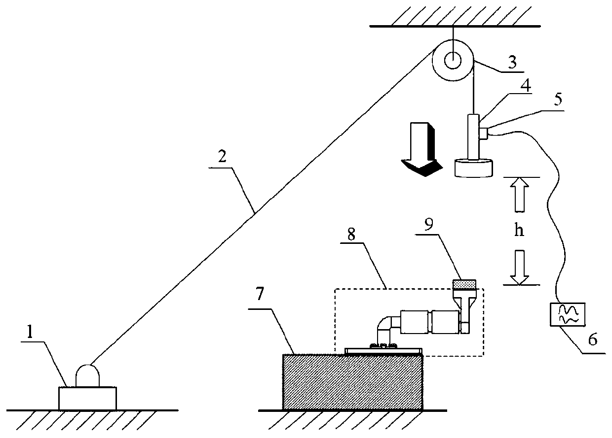
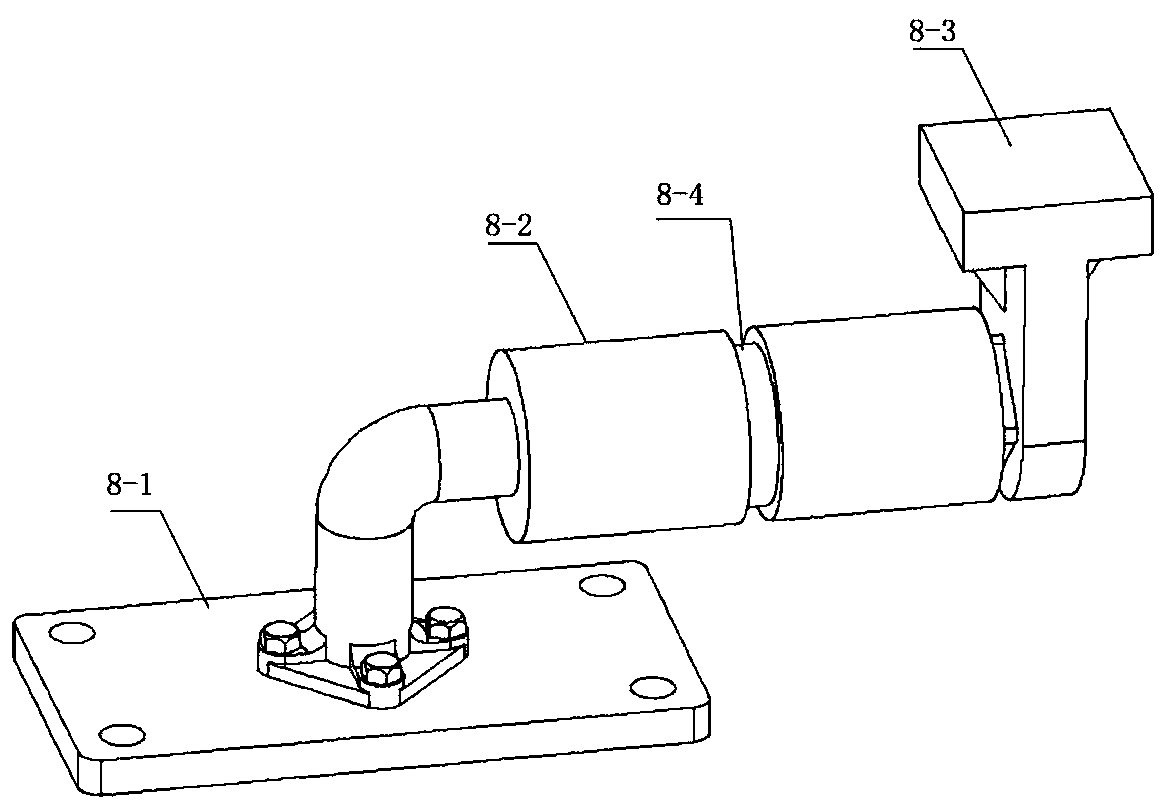
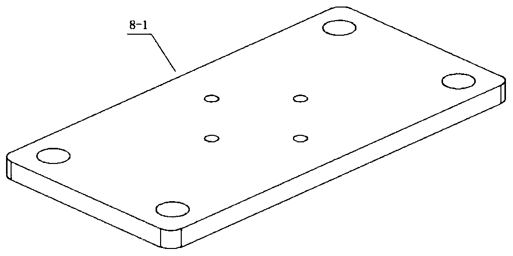
[0036] Such as figure 1As shown, the present invention discloses a dynamic load shearing test device for emergency breaking self-sealing structure, including a fixed pulley block assembly and a drop weight assembly, which specifically includes a fixed table 1, a steel wire rope 2, a fixed pulley 3, and a drop weight 4 , acceleration sensor 5, dynamic signal analyzer 6, fixed test platform 7, clamping device for structural parts 8, base 8-1, structural parts 8-2, dynamic load loading platform 8-3, reinforcing rib 8-31, internal thread 8-32, force surface 8-33, rubber pad 9. Both the fixed platform 1 and the fixed test platfo...


PUM


Abstract

The invention discloses a dynamic load shear test device and method for an emergency disconnection self-sealing structure, and belongs to the technical field of emergency disconnection testing. The device comprises a structural member, a base, a dynamic load loading platform, a fixed pulley, a drop hammer and a rubber pad, wherein the base is fixed for supporting the structural member; the dynamicload loading platform is connected to the structural member; and the drop hammer is suspended directly above the bearing surface of the dynamic load loading platform through a steel wire rope and thefixed pulley. The test device provided by the invention is simple in structure, convenient to process and simple to operate, can realize the shear test of the structural member under different impactloads, and can further limit the load application time and the change of the clamp speed at the same time, thereby reflecting the mechanical behavior of the structural member under different impact energies, supplementing the blanks in the research on the dynamic load shear test of the emergency disconnection self-sealing structure, and being of great significance for further examining the qualification of the emergency disconnection self-sealing structure and further standardizing the use conditions of the emergency disconnection self-sealing structure.

Description

technical field [0001] The invention relates to a dynamic load shearing test device and method for an emergency disconnection self-sealing structure, belonging to the technical field of emergency disconnection testing. Background technique [0002] The emergency disconnect self-sealing structure is an indispensable unit in aviation hydraulic, liquid cooling and fuel systems. It is a pre-set weak area in a certain part of the self-sealing structure, which is often used for the connection between the fuel tank and the fuel conduit, and the connection between the fuel tank and the fuel tank. And the structural deformation of the helicopter may cause the fuel system to destroy some points of the connection. In an emergency situation, such as when the aircraft crashes or there is a risk of crashing, it is required that the emergency disconnection self-sealing structure is subjected to a certain load, and its weak area is fractured to protect the fuel system. At the same time, in...

Claims


Application Information

Patent Timeline
Patent Type & Authority Applications(China)
IPC IPC(8): G01N3/303G01N3/02
CPCG01N3/02G01N3/303G01N2203/001G01N2203/0025G01N2203/0039G01N2203/0067
Inventor 周光明邓健任涛徐庆华
Owner NANJING UNIV OF AERONAUTICS & ASTRONAUTICS
Why Eureka
Try Eureka