
Flexible structure, display panel and display device

A flexible structure and display panel technology, applied in identification devices, nonlinear optics, instruments, etc., can solve problems such as easy pad misalignment, pad misalignment, and affecting the normal display of the display panel, so as to improve the reliability of binding, The effect of reducing design difficulty and improving binding yield

Active Publication Date: 2022-05-10
KUNSHAN GO VISIONOX OPTO ELECTRONICS CO LTD
View PDF17 Cites 0 Cited by
  • Summary
  • Abstract
  • Description
  • Claims
  • Application Information

AI Technical Summary

Problems solved by technology

[0002] With the improvement of the resolution of the flexible display panel, the size of the pads in the binding area of ​​the flexible display panel gradually decreases, and the density of the pads gradually increases. The size of the pads is also gradually reduced, and the density of the pads is gradually increased, which makes it easy for the pads to be misaligned or even open when the flexible display panel is bound to the flexible structure.
[0003] In addition, the deformation of the flexible display panel and the flexible structure during the bending process, as well as temperature and humidity factors also make it easy for the gasket to be misplaced or even short-circuited when the flexible display panel and the flexible structure are bound, which affects the connection between the flexible structure and the flexible display panel. The signal transmission process will affect the normal display of the display panel

Method used


Image

  • Flexible structure, display panel and display device
  • Flexible structure, display panel and display device
  • Flexible structure, display panel and display device

Examples


Embodiment Construction

[0036] The present invention will be further described in detail below in conjunction with the accompanying drawings and embodiments. It should be understood that the specific embodiments described here are only used to explain the present invention, but not to limit the present invention. In addition, it should be noted that, for the convenience of description, only some structures related to the present invention are shown in the drawings but not all structures. Throughout this specification, the same or similar reference numerals represent the same or similar structures, elements or processes. It should be noted that, in the case of no conflict, the embodiments in the present application and the features in the embodiments can be combined with each other.

[0037] As in the background technology, with the improvement of the resolution of the flexible display panel, a large amount of data input and data output are required in the flexible display panel, the size of the pads...


PUM


Abstract

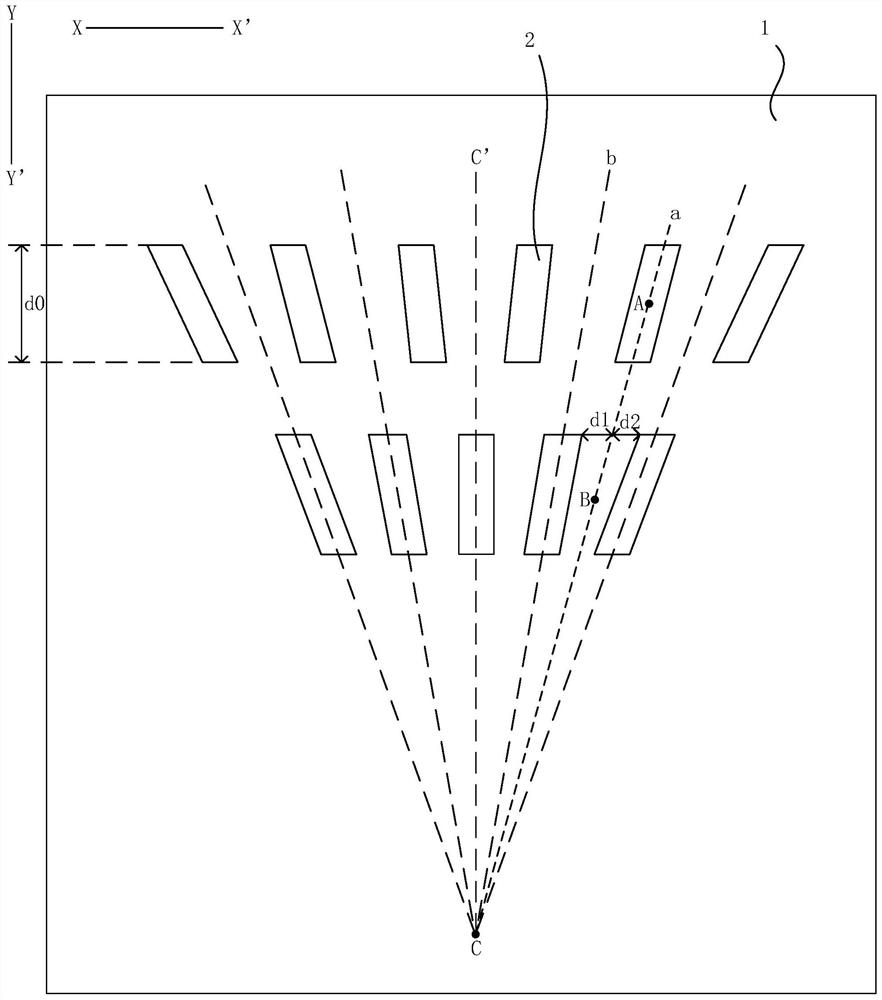
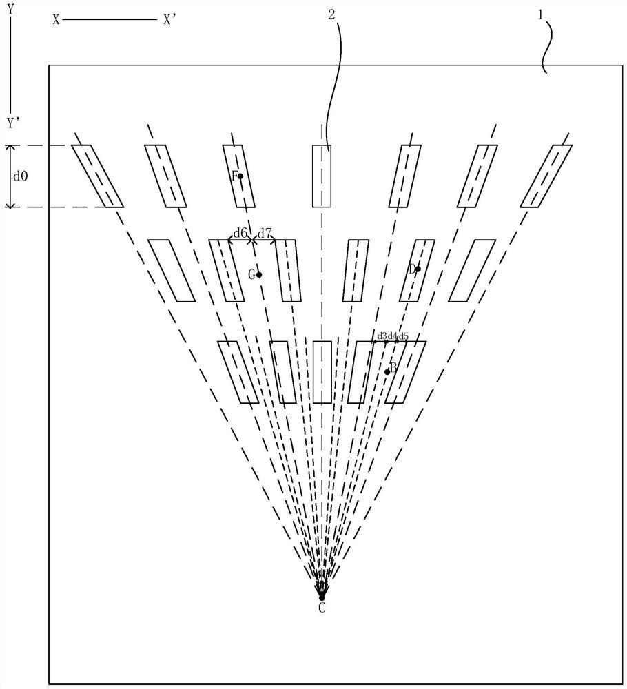
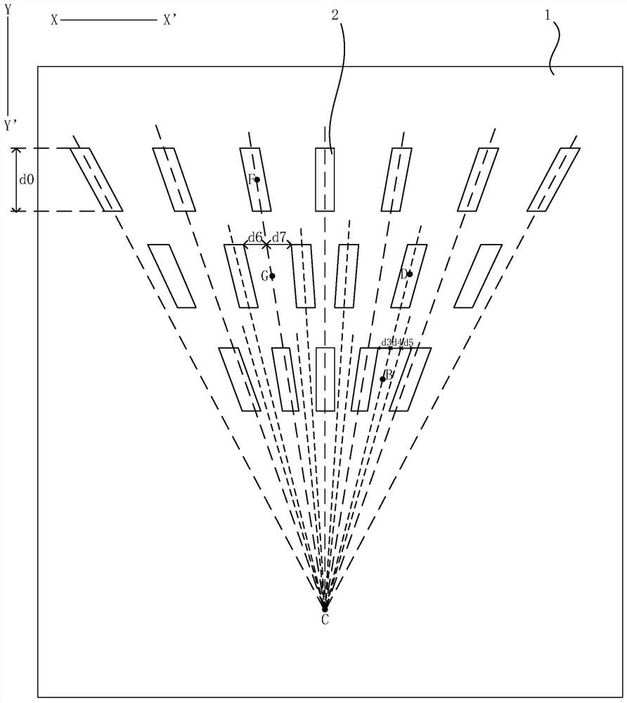
The invention discloses a flexible structure, a display panel and a display device. The flexible structure includes a base material; n rows of first pads located on one side of the base material, and each row of first pads is arranged along a first direction; the first pads The virtual extension line of is set obliquely relative to the reference line along the second direction, and the virtual extension lines of all the first pads intersect at the same convergence point; wherein, the first direction and the second direction are perpendicular to each other; the i+1th row first The center point of the pad along the first direction, the first set bisection point among the m bisection points of the space between two adjacent first pads in the i-th row of the first pad along the first direction, and the convergence The points are correspondingly located on the same straight line; where, n is an integer greater than 1, i is a positive integer, i is less than n, and m is equal to n‑i+1. Through the technical solution of the present invention, the binding yield and binding reliability between the flexible display panel and the flexible structure are improved, and the design difficulty of the first pad in the flexible structure is reduced.

Description

technical field [0001] Embodiments of the present invention relate to the field of display technology, and in particular to a flexible structure, a display panel and a display device. Background technique [0002] As the resolution of the flexible display panel increases, the size of the pads in the binding area of ​​the flexible display panel gradually decreases, and the density of the pads gradually increases. Similarly, pads on the flexible structure attached to the corresponding binding area are required The size of the pads is also gradually reduced, and the density of the pads is gradually increased, which makes it easy for the pads to be misaligned or even open when the flexible display panel is bound to the flexible structure. [0003] In addition, the deformation of the flexible display panel and the flexible structure during the bending process, as well as temperature and humidity factors also make it easy for the gasket to be misplaced or even short-circuited when...

Claims


Application Information

Patent Timeline
Patent Type & Authority Patents(China)
IPC IPC(8): G09F9/30H10K99/00
CPCG09F9/301H10K59/82H10K77/111G06F1/1652G02F1/13458G02F1/133305Y02E10/549H10K59/131H10K2102/311G02F1/136286H10K50/80
Inventor 朱昆鹏王向前彭兆基
Owner KUNSHAN GO VISIONOX OPTO ELECTRONICS CO LTD
Learn More