Secondary battery, battery module and electric device
A secondary battery and cell technology, applied to battery pack parts, battery cover/end cover, battery box/outer, etc., can solve the problems of high structural cost, increase the internal space of the cell, and many processes, and achieve simplification Effect of production process, improvement of flow performance, and increase of contact area
- Summary
- Abstract
- Description
- Claims
- Application Information
AI Technical Summary
Problems solved by technology
Method used
Image
Examples
Embodiment approach 1
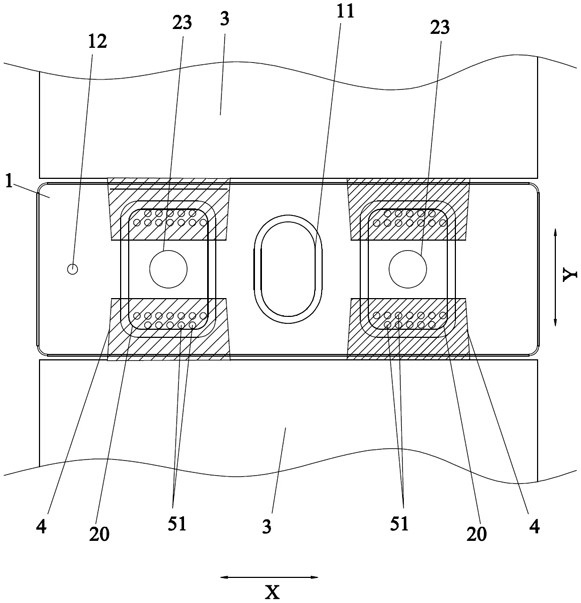
[0050] A secondary battery includes a top cover sheet 1, a cell assembly, and an insulating member 9 disposed between the top cover sheet 1 and the cell assembly to isolate the cell assembly and the top cover sheet 1; at least one cell assembly, cell The assembly includes the cell body 3 and the tab 4 provided on the cell body 3; the pole 2, the pole 2 passes through the top cover sheet 1 and the insulator 9 and is connected to the tab 4; the lower end of the pole 2 is along the insulator The lower surface of 9 is extended to form an extension part 20 , and the extension part 20 is fixedly connected with the tab 4 .
[0051] Because in the existing structure, the cell lug is super-welded with the adapter piece first, and then placed on the bottom of the top cover pole for laser welding to realize the function of the cell, but this structure has high cost, many processes, and the transfer The thickness of the sheet will also increase the internal space of the cell. Therefore, a...
Embodiment approach 2
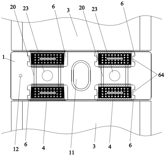
[0062] The difference from Embodiment 1 is that this embodiment includes two battery core bodies 3, where the two tabs 4 of one battery core body 3 are fixedly connected to the extensions 20 of the two poles 2, and the other battery core body The two tabs 4 of 3 are also fixedly connected to the extensions 20 of the two poles 2 respectively. In this embodiment, the cell bodies 3 are arranged side by side, and the two tabs 4 with the same polarity are connected to the extension 20 of the same pole 2, and the extension 20 is arranged around the edge of the main body 23, so that the same extension 20 can connect two tabs 4 with the same polarity, that is to realize the parallel connection between two cell bodies 3, increase the number of cell bodies 3 in the battery, and help to increase the energy density of the battery.
[0063] In addition, in some embodiments, four cell bodies 3 may also be included. Specifically, four cell assemblies are arranged side by side along the width...
Embodiment approach 3
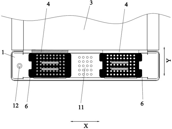
[0066] The difference from the first embodiment is that this embodiment also includes a protective piece 6, the protective piece 6 includes a second connecting portion 61 and a second bending portion 62 connected in sequence, and the second connecting portion 61 is fixed to the first connecting portion by welding 41, the second bending portion 62 is bent along the inner surface of the first bending portion 42, the first connecting portion 41 and the second connecting portion 61 form a second welding footprint by welding, and the protection member 6 also includes The turning portion 63 is connected to the second bending portion 62 , and the second connecting portion 61 , the second bending portion 62 and the turning portion 63 form a U-shaped structure. In this embodiment, the protection piece 6 is added to prevent the folded part of the tab 4 from being inserted into the cell body 3; to prevent the burrs generated by welding from passing through the tab 4 and even inserting int...
PUM
 Abstract
Description
Claims
Application Information
 - R&D
- Intellectual Property
- Life Sciences
- Materials
- Tech Scout
- Unparalleled Data Quality
- Higher Quality Content
- 60% Fewer Hallucinations
Browse by: Latest US Patents, China's latest patents, Technical Efficacy Thesaurus, Application Domain, Technology Topic, Popular Technical Reports.
© 2025 PatSnap. All rights reserved.Legal|Privacy policy|Modern Slavery Act Transparency Statement|Sitemap|About US| Contact US: help@patsnap.com


