Novel dielectric filter coupling structure

A dielectric filter and coupling structure technology, which is applied in the field of communication, can solve the problems of complex capacitive coupling structure and difficult process realization, and achieve the effect of small negative coupling

Pending Publication Date: 2020-01-14
苏州瑞玛精密工业股份有限公司
View PDF0 Cites 1 Cited by
  • Summary
  • Abstract
  • Description
  • Claims
  • Application Information

AI Technical Summary

Problems solved by technology

At present, there is a miniaturized filter, that is, a solid dielectric filter, which is widely used, but the structure of realizing capacitive coupling (or negative coupling) in a solid dielectric filter is relatively complicated, the process is difficult to realize, and it is easy to cause the passband Nearer frequencies produce spurious passbands. Therefore, how to provide a dielectric filter with a simple structure and low process difficulty has become a research direction for those skilled in the art.

Method used


Image

  • Novel dielectric filter coupling structure

Examples


Embodiment 1

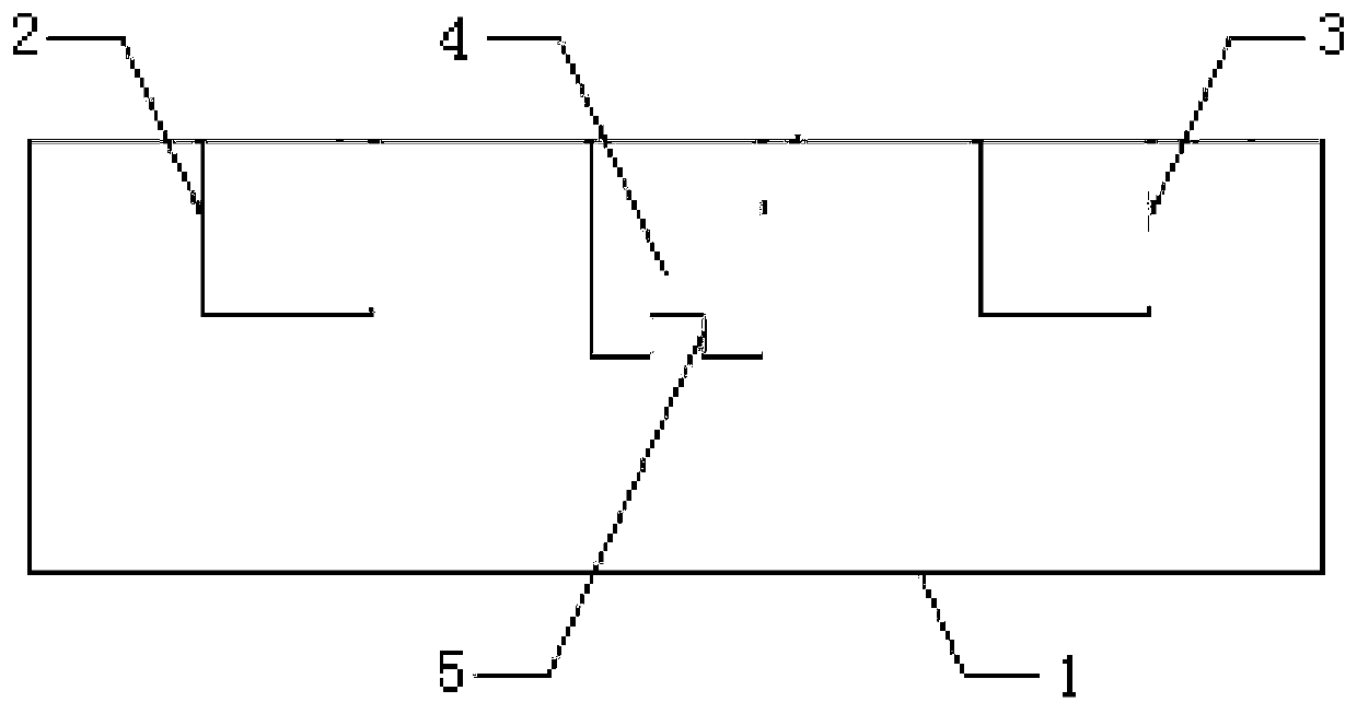
[0018] Embodiment 1: A new type of dielectric filter coupling structure, including a dielectric filter body 1, a first blind hole 2 and a second blind hole 3, the first blind hole 2 and the second blind hole 3 are arranged in the dielectric filter On the same side of the filter body 1, the first blind hole 2 and the second blind hole 3 form two dielectric resonators with the medium on the dielectric filter body 1, and a negative coupling hole is arranged between the two dielectric resonators 4. The openings of the negative coupling hole 4 and the first debugging hole 2 and the second debugging hole 3 are located on the same surface of the dielectric filter body 1. One end of the negative coupling hole 4 runs through the dielectric filter body 1, and the other end is a closed end , the negative coupling hole 4 is provided with a boss 5, the boss 5 is integrated with the dielectric filter body 1, and the inner wall of the negative coupling hole 4 and the outer wall of the boss 5 ...

Embodiment 2

[0023] Embodiment 2: A new type of dielectric filter coupling structure, including a dielectric filter body 1, a first blind hole 2 and a second blind hole 3, the first blind hole 2 and the second blind hole 3 are arranged in the dielectric filter On the same side of the filter body 1, the first blind hole 2 and the second blind hole 3 form two dielectric resonators with the medium on the dielectric filter body 1, and a negative coupling hole is arranged between the two dielectric resonators 4. The openings of the negative coupling hole 4 and the first debugging hole 2 and the second debugging hole 3 are located on the same surface of the dielectric filter body 1. One end of the negative coupling hole 4 runs through the dielectric filter body 1, and the other end is a closed end , the negative coupling hole 4 is provided with a boss 5, the boss 5 is integrated with the dielectric filter body 1, and the inner wall of the negative coupling hole 4 and the outer wall of the boss 5 ...


PUM


Abstract

The invention discloses a novel dielectric filter coupling structure, which includes a dielectric filter body, a first blind hole, and a second blind hole. The first blind hole and the second blind hole are disposed on the same side of the dielectric filter body. The first and second blind holes and a dielectric on the dielectric filter body form two dielectric resonators. A negative coupling holeis arranged between the two dielectric resonators. The negative coupling hole and the openings of the first and second debugging holes are located on the same surface of the dielectric filter body. One end of the negative coupling hole penetrates through the dielectric filter body, and the other end of the negative coupling hole is a closed end. The negative coupling hole is provided therein witha boss. The boss and the dielectric filter body constitute an integrated structure. A continuous conductive layer is disposed on the inner wall of the negative coupling hole and the outer wall of theboss. The novel dielectric filter coupling structure controls the far-end parasitic pass-band frequency while realizing capacitive coupling.

Description

technical field [0001] The invention relates to a novel dielectric filter coupling structure, which belongs to the technical field of communication. Background technique [0002] With the development of wireless communication technology, the distribution of wireless communication base stations is becoming more and more dense, and the volume requirements of base stations are getting smaller and smaller. Among them, the RF front-end filter module accounts for a relatively large volume in the base station. Therefore, the size of the filter The volume requirement is also getting smaller and smaller. However, when reducing the volume of the metal coaxial cavity filter, it is found that the smaller the volume of the filter, the greater the surface current, the greater the loss, and the lower the power bearing capacity, that is, the smaller the power capacity. That is to say, as the volume of the metal coaxial cavity filter decreases, its performance index becomes worse. At prese...

Claims


Application Information

Patent Timeline
Patent Type & Authority Applications(China)
IPC IPC(8): H01P1/20
CPCH01P1/2002
Inventor 徐华
Owner 苏州瑞玛精密工业股份有限公司
Why Eureka
Try Eureka