Top drive load measurement weight on bit

A hook load, drilling rig technology, applied in the direction of drill pipe, drill pipe, earthwork drilling, etc., can solve problems such as accuracy limitations, achieve high accuracy, overcome shortcomings and problems

Pending Publication Date: 2020-01-14
SCHLUMBERGER TECH LTD BV
View PDF18 Cites 0 Cited by
  • Summary
  • Abstract
  • Description
  • Claims
  • Application Information

AI Technical Summary

Problems solved by technology

In fact, monitoring loads via horizontal load pins designed to monitor shear forces has limitations in accuracy

Method used


Image

  • Top drive load measurement weight on bit
  • Top drive load measurement weight on bit
  • Top drive load measurement weight on bit

Examples


Embodiment Construction

[0026] Given the general discussion below, by referring to the following Figure 1 to Figure 7B The preferred embodiments can be better understood. The present disclosure may be more readily understood in the context of a high-level description of certain embodiments.

[0027] Embodiments of the present invention provide a top drive with a higher accuracy load measurement system in which the strain gauges can be built into the vertical tie rods used to suspend the top drive from the traveling block. This solution allows built-in strain gauges to monitor only tensile stress (and not shear), where tensile stress measurement can be performed with very high accuracy.

[0028] A tie rod with a built-in weight-on-bit sensor was tested. The purpose of the test was to verify that the tie rods with built-in strain gauges (WOB sensors) provided 99.5% load measurement accuracy over the entire range and 99.7% load measurement accuracy from 5% to 50%. The test was performed on a set of ...


PUM


Abstract

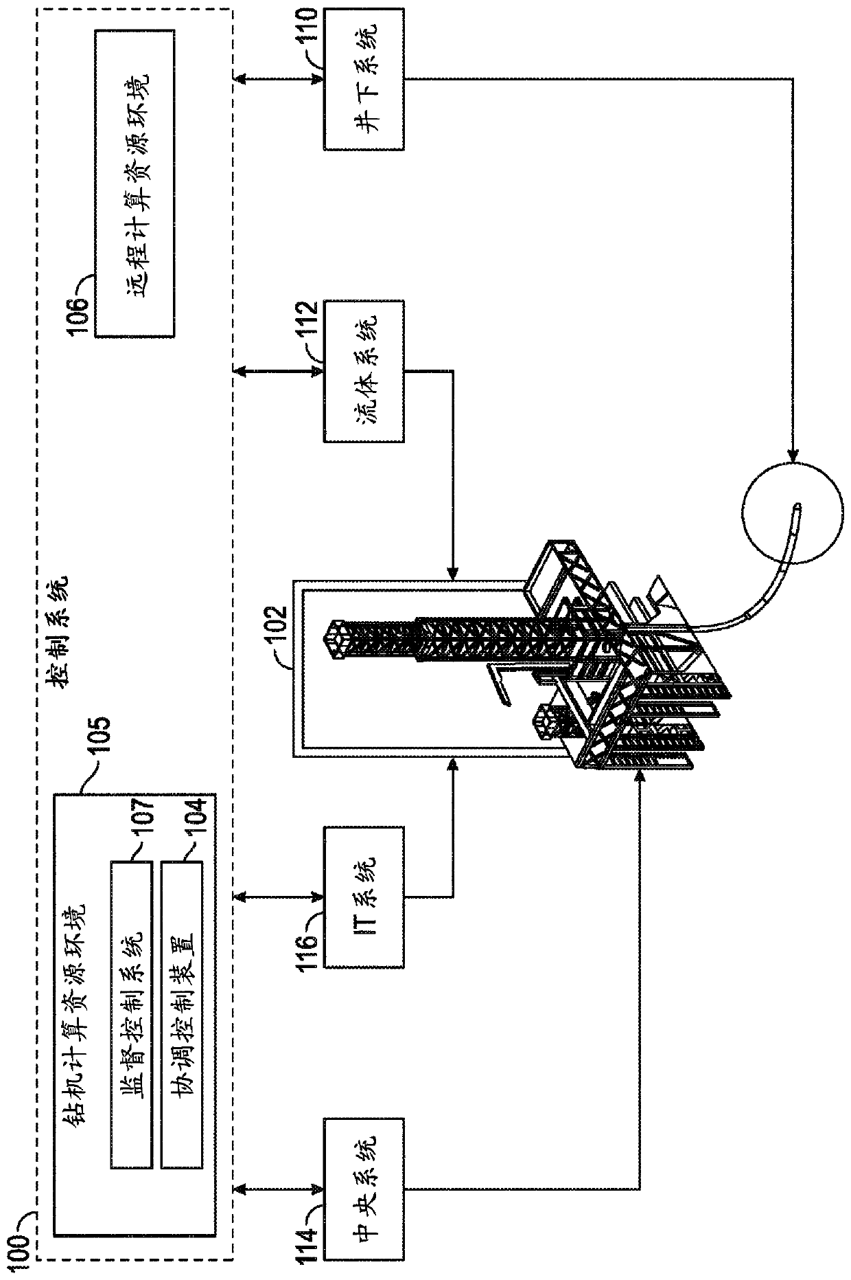
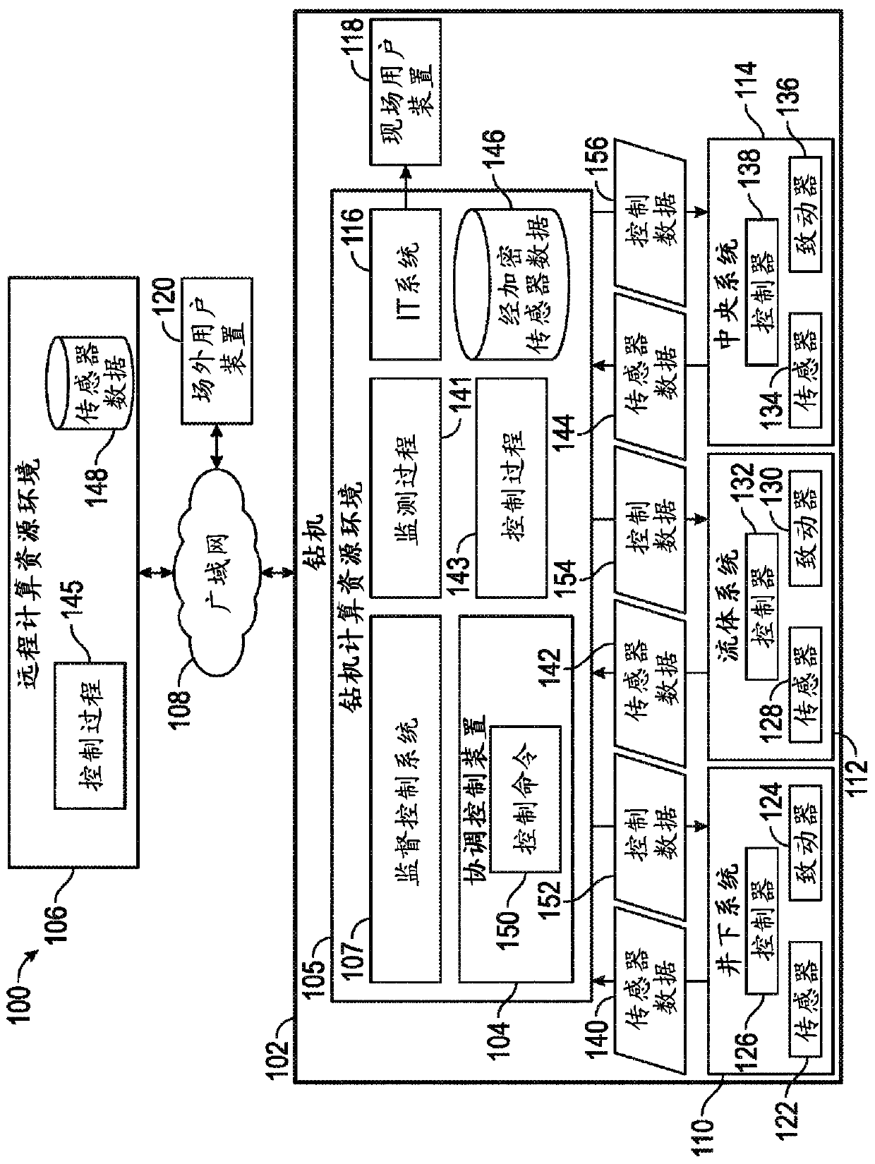
A system for monitoring a drilling rig condition, the system comprising: a travelling block suspended via a drilling line from a crown block at the top of a mast of the drilling rig; a frame to whichthe drilling tools and/or a pipe string is mounted; at least one tie rod that connects the frame to the travelling block, wherein the at least one tie rod comprises a tensile sensor; and a control system that receives a signal corresponding to tension sensed by the tensile sensor, wherein the control system determines a drilling rig condition based at least in part on the signal received from thetensile sensor.

Description

technical field [0001] The present disclosure relates generally to the field of drilling. More particularly, the present invention relates to methods and apparatus for driving top drives in drilling systems. Background technique [0002] Top drives are used to suspend and rotate drill strings and / or casings in drilling applications. The top drive is supported by a drilling wire rope wound on a set of sheaves, which is connected to the winch at one end and to a dead line retainer at the other end. The top drive supports the drill string via thrust bearings. Mud can be pumped into the drill string via a swivel. Additionally, top drives typically include one or more motors (electric or hydraulic) that generate rotation of the drill string. Reactive torque applied to the top drive may be transmitted to the drill frame via a top drive carriage that rides on the drill frame rails. [0003] Various measurements may be taken to manage the drilling process, including measurement...

Claims


Application Information

Patent Timeline
Patent Type & Authority Applications(China)
IPC IPC(8): E21B44/00E21B3/02G08C17/02
CPCE21B3/02E21B44/00E21B19/02G01L5/0061E21B3/022
Inventor 布琳朱路易·艾斯奥依维德·欧利姆斯泰德马格努斯·伯格
Owner SCHLUMBERGER TECH LTD BV
Why Eureka
Try Eureka