
A T-shaped guide rail automatic polishing and unloading equipment

An automatic polishing and guide rail technology, which is applied in the direction of grinding/polishing equipment, metal processing equipment, surface polishing machine tools, etc., can solve the problems of waste of human resources, single function of polishing equipment, time-consuming and labor-intensive, etc., to achieve reasonable structure and high efficiency. Guarantee the polishing quality and improve the polishing efficiency

Active Publication Date: 2021-08-10
万秀芬
View PDF15 Cites 0 Cited by
  • Summary
  • Abstract
  • Description
  • Claims
  • Application Information

AI Technical Summary

Problems solved by technology

[0004] 1. Due to the unreasonable structure and low degree of automation, the existing polishing equipment cannot effectively and quickly polish the T-shaped guide rail;
[0005] 2. The existing polishing equipment has a single function, only one set of polishing wheels, which cannot be thoroughly polished to achieve the required bright and flat surface;
[0006] 3. Unloading cannot be completed automatically, which is time-consuming and labor-intensive, wasting a lot of human resources;
[0007] 4. The existing polishing equipment does not have multiple sets of all-round polishing wheels, and cannot fully and effectively polish the T-shaped guide rail

Method used


Image

  • A T-shaped guide rail automatic polishing and unloading equipment
  • A T-shaped guide rail automatic polishing and unloading equipment
  • A T-shaped guide rail automatic polishing and unloading equipment

Examples


Embodiment Construction

[0027] The preferred embodiments of the present invention will be described in detail below in conjunction with the accompanying drawings, so that the advantages and features of the present invention can be more easily understood by those skilled in the art, so as to define the protection scope of the present invention more clearly.

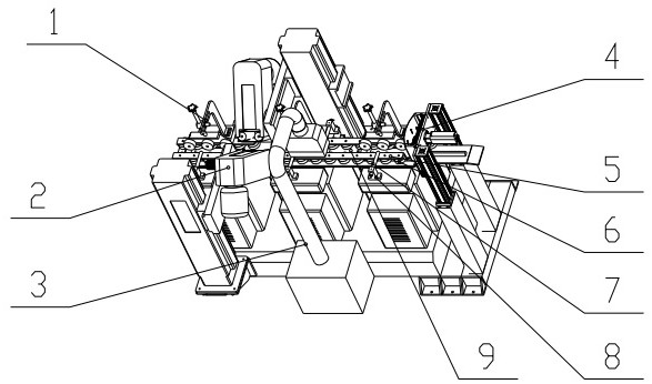
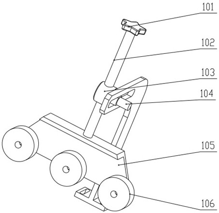
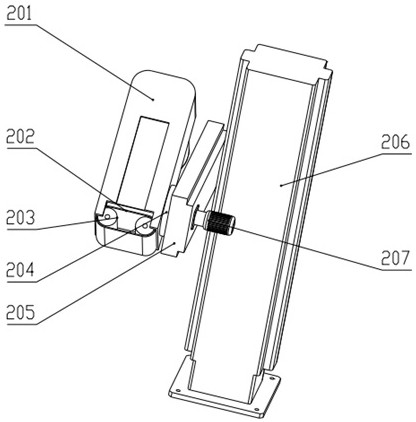
[0028] Examples, see figure 1 , figure 2 , image 3 , Figure 4 , Figure 5 As shown, a T-shaped guide rail automatic polishing and unloading equipment includes: top surface polishing assembly 1, side polishing assembly 2, vacuum cleaner 3, unloading assembly 4, clamping plate 5, clamping roller 6, first slide bar 7 , a support frame 8 and a conveyor belt 9, a conveyor belt 9 is arranged in the middle of the upper part of the support frame 8, and a top polishing assembly 1, a side polishing assembly 2, a vacuum cleaner 3 and The unloading assembly 4 is movably connected with one end of the first slide bar 7 on the support frame 8, and the ot...


PUM


Abstract

A T-shaped guide rail automatic polishing and unloading equipment, including a top surface polishing assembly, a side surface polishing assembly, a vacuum cleaner, an unloading assembly, a clamping plate, a clamping roller, a first slide bar, a support frame and a conveyor belt, a top surface polishing assembly, The side polishing assembly and the vacuum cleaner are installed on both sides of the conveyor belt, and are fixed on the support frame by bolts. The unloading assembly is fixed on one end of the support frame by bolts. It is movably connected, and the clamping rollers are evenly fixed on the bottom surface of the clamping plate. The equipment is equipped with multiple sets of top surface polishing components and side surface polishing components to ensure that the T-shaped guide rail is polished to the required bright and flat surface; the top surface polishing components and side surfaces The position of the polishing components can be adjusted to achieve a suitable bonding force and polishing angle. There is no dead angle in the polishing, which effectively ensures the polishing quality; the structure of the unloading component is reasonable and efficient, and it can quickly unload the polished T-shaped guide rail to improve the polishing quality. efficiency.

Description

technical field [0001] The invention relates to the technical field of polishing automation, in particular to an automatic polishing and unloading device for a T-shaped guide rail. Background technique [0002] Polishing refers to the use of mechanical, chemical or electrochemical effects to reduce the surface roughness of the workpiece to obtain a bright and flat surface. It is a modification of the surface of the workpiece using polishing tools and abrasive particles or other polishing media. T During the use of the T-shaped guide rail, rust will be generated, which will reduce the flatness of the guide rail, and then affect the normal use of the guide rail; therefore, polishing the surface of the T-shaped guide rail is a very important process. [0003] In view of the above technical problems, the applicant searched the prior art and found that the Chinese invention patent application number: 201611075330.2 discloses a polishing machine, which includes a base, a polishing...

Claims


Application Information

Patent Timeline
Patent Type & Authority Patents(China)
IPC IPC(8): B24B21/00B24B21/04B24B27/00B24B29/02B24B41/00B24B41/06B24B47/12B24B47/22B24B55/06B24B55/08
CPCB24B21/006B24B21/008B24B21/04B24B27/0023B24B27/0069B24B27/0076B24B29/02B24B41/005B24B41/06B24B47/12B24B47/22B24B55/06B24B55/08
Inventor 吴胜奎
Owner 万秀芬
Learn More