
Double-layer composite mold and mounting method

A double-layer, mold technology, applied in the direction of mold fixtures, mold auxiliary parts, manufacturing tools, etc., can solve the problems of low reuse rate and inflexible rib spacing, so as to improve versatility, flexibility, and sealing gap effect

Pending Publication Date: 2020-01-17
中建科技成都有限公司
View PDF0 Cites 2 Cited by
  • Summary
  • Abstract
  • Description
  • Claims
  • Application Information

AI Technical Summary

Problems solved by technology

[0003] The purpose of the present invention is to provide a double-layer laminated mold and its installation method to solve the problems of inflexible rib spacing and low reuse rate of the laminated plate mold in the prior art, realize flexible rib spacing, improve versatility and purpose of reuse

Method used


Image

  • Double-layer composite mold and mounting method
  • Double-layer composite mold and mounting method
  • Double-layer composite mold and mounting method

Examples


Embodiment 1

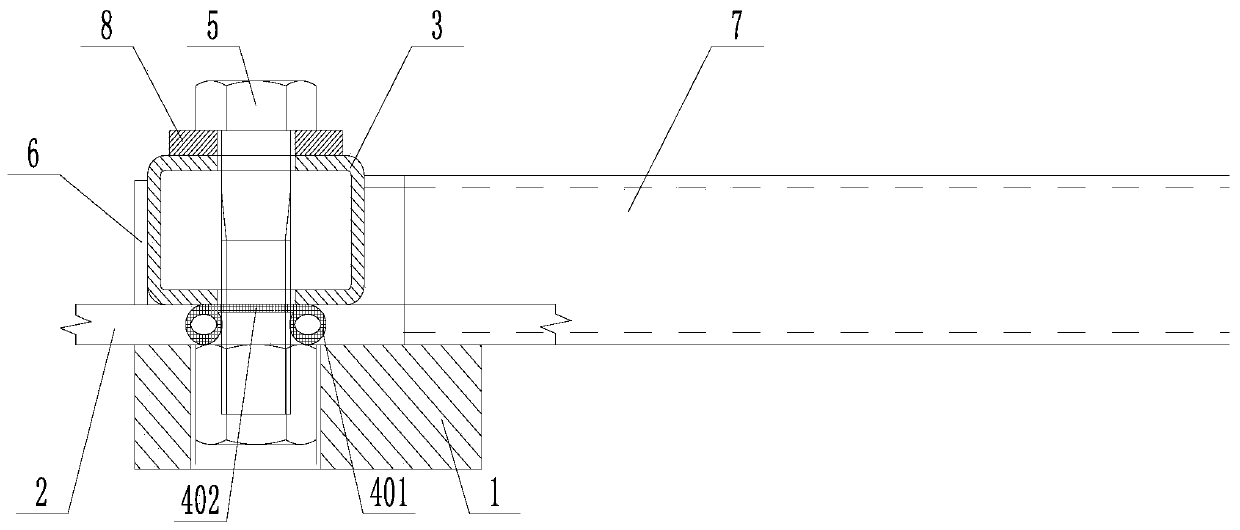
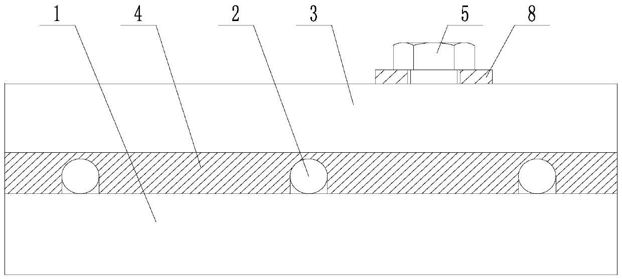
[0032] Such as Figure 2 to Figure 4 A double-layer laminated mold is shown, including a bottom plate 1, a steel bar 2 passing through the pouring area, and a connecting piece 3 above the bottom plate 1, and the steel bar 2 is located between the bottom plate 1 and the connecting piece 3 A seal 4 is also provided between the bottom plate 1 and the connecting piece 3 , and the bottom plate 1 and the connecting piece 3 are fixedly connected by bolts 5 .

[0033] In this embodiment, a connecting piece 3 is arranged above the bottom plate 1, and the steel bar 2 passes between the two, and the effect of clamping the steel bar 2 is realized by utilizing the gravity of the connecting piece 3 and the fastening of the bolts. A sealing member 4 is also arranged between the bottom plate 1 and the connecting member 3 to seal the gap and prevent the slurry from running and leaking. In this embodiment, the spacing of the reinforcing bars 2 is no longer a constraint of the pouring structure...

Embodiment 2

[0037] Such as Figure 2 to Figure 4 In the shown double-layer laminated mold, on the basis of Example 1, the bottom plate 1 is rectangular, and the connector 3 is a rectangular tube, and the long axis of the rectangular tube is parallel to the long axis of the bottom plate 1 ; The width of the bottom plate 1 is greater than the width of the rectangular tube. The profiled steel plate 6 is welded on the forming surface of the rectangular tube. The side surface of the checkered steel plate 6 facing the pouring area is coplanar with the side surface of the bottom plate 1 facing the pouring area. Said sealing element 4 is laid between the base plate 1 and the connecting element 3 and encloses the reinforcement 2 from above. The sealing member 4 is an EPDM rubber strip; the sealing member 4 includes two hollow tube parts 401 , and the tops of the two hollow tube parts 401 are fixedly connected by a rubber part 402 . The bottom plate 1 is a steel plate. It also includes a pressi...


PUM


Abstract

The invention discloses a double-layer composite mold and a mounting method. The double-layer composite mold comprises a bottom plate, and a steel bar penetrating out of a pouring area and further comprises a connecting piece located above the bottom plate, the steel bar is located between the bottom plate and the connecting piece, a sealing piece is further arranged between the bottom plate and the connecting piece, and the bottom plate is fixedly connected to the connecting piece through a bolt. According to the double-layer composite mold and the mounting method, the problems of inflexiblebar outlet spacing and low repeated using rate of a composite plate mold in the prior art are solved, and the purposes of achieving flexible bar outlet spacing and improving universality and repeatedusing rate are achieved.

Description

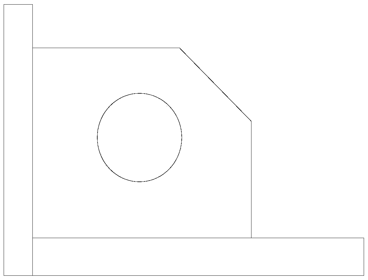
technical field [0001] The invention relates to the field of concrete pouring molds, in particular to a double-layer composite mold and an installation method. Background technique [0002] In the field of civil engineering, the pouring of reinforced concrete is one of the most important tasks. In the process of pouring all kinds of plates or profiles, whether it is cast on site or prefabricated in advance, molds are required. With the continuous improvement of casting technology, traditional formwork types can no longer meet the increasingly diverse casting needs, so laminated plate molds appear. In the prior art, the angle iron laminated plate mold is the advanced representative, such as figure 1 As shown, it can easily set up steel bars and facilitate the rapid pouring of reinforced concrete members. However, the existing angle iron laminated plate mold has the following disadvantages: 1) It is suitable for a small number of component sizes, and the size of the rib spa...

Claims


Application Information

Patent Timeline
Patent Type & Authority Applications(China)
IPC IPC(8): B28B7/00
CPCB28B7/0002B28B7/0011B28B7/0014
Inventor 乔龙肖晓刘昌任伟赖力杨伟罗奎
Owner 中建科技成都有限公司
Learn More