Corrugated steel plate composite beam without upper flange and manufacturing method thereof

A technology of corrugated steel plates and composite beams, applied in bridges, bridge parts, bridge materials, etc., can solve the problems of inconvenience, complex construction process, and large amount of steel.

Pending Publication Date: 2020-01-17
ZHEJIANG PROVINCIAL INST OF COMM PLANNING DESIGN & RES CO LTD
View PDF2 Cites 1 Cited by
  • Summary
  • Abstract
  • Description
  • Claims
  • Application Information

AI Technical Summary

Problems solved by technology

[0003] In the structural design of bridges built with steel structures, steel plate composite girders, as a medium- and small-span bridges, have full-life economic advantages, which combine the advantages of steel bridges and concrete bridges, making structural design, construction, and maintenance more Because it is reasonable, it has been promoted rapidly in recent years. For example, the patent document with the notification number CN109648272A discloses a prefabrication method for prefabricated steel girders in steel plate composite girders. It is all prefabricated I-shaped beams, that is, there are upper flange plates, Therefore, when it is used in small and medium-span bridges, there are problems such as excessive steel consumption, complicated construction technology and inconvenience.

Method used


Image

  • Corrugated steel plate composite beam without upper flange and manufacturing method thereof
  • Corrugated steel plate composite beam without upper flange and manufacturing method thereof
  • Corrugated steel plate composite beam without upper flange and manufacturing method thereof

Examples


Embodiment

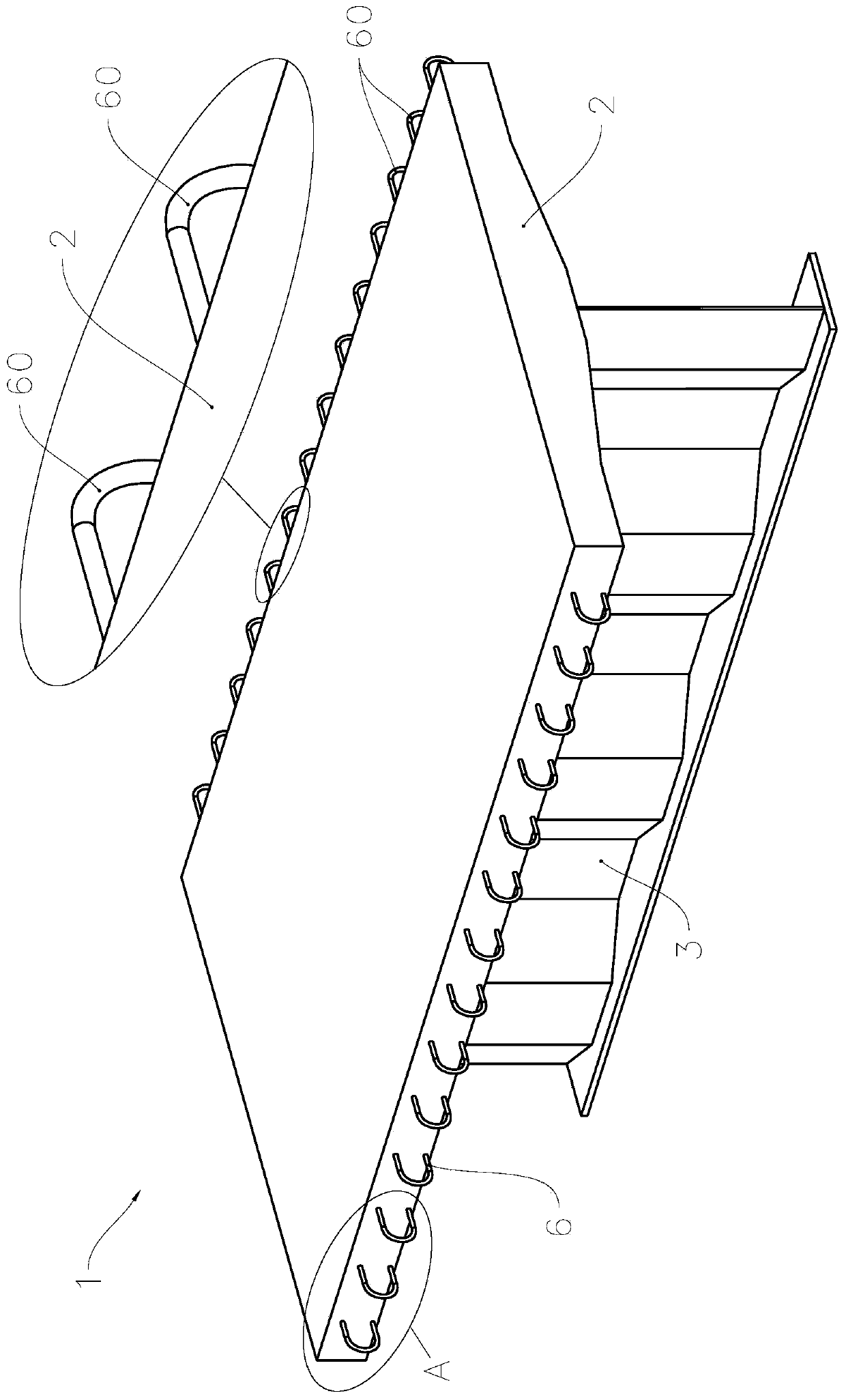
[0031] see Figure 1 to Figure 6 , the corrugated steel plate composite girder 1 of the present invention has no upper flange plate structure, and specifically includes a prefabricated steel girder 3 and a concrete bridge deck 2 fixedly connected with the prefabricated steel girder 3 .

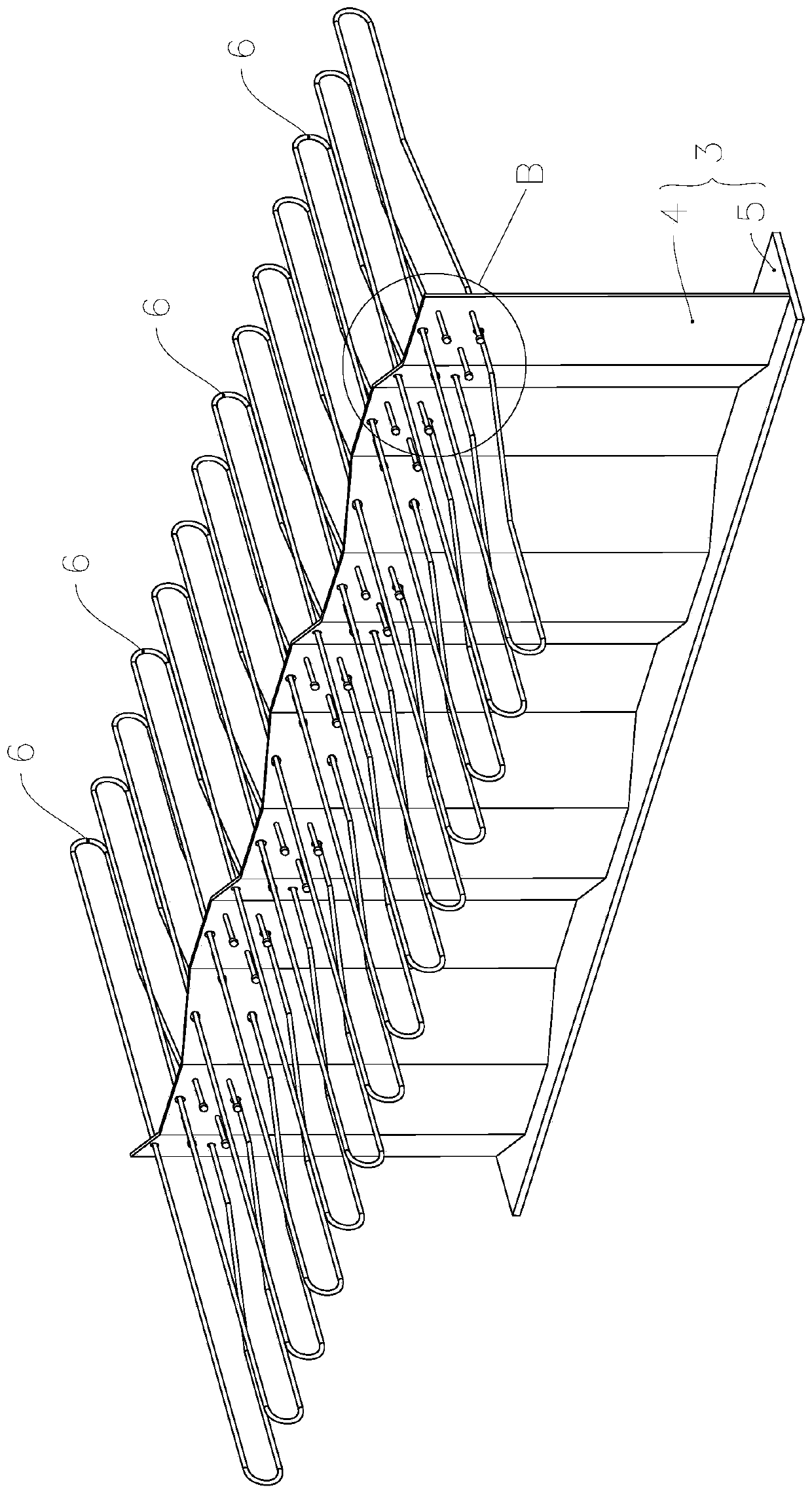
[0032] The prefabricated steel girder 3 includes a web 4 and a bottom plate 5; wherein, the web 4 is a corrugated steel plate arranged vertically along the groove length direction, the bottom plate 5 is a strip-shaped straight steel plate, and the lower edge of the web 4 is connected to the upper surface of the bottom plate 5 Welding is fixed, and the welding trace extends along the length direction of the web 4 to cover the joint surface of the two, so that the web 4 and the bottom plate 5 firmly form an inverted T-shaped structure. In addition, the web 4 and the bottom plate 5 may also be fixedly connected by bolting.

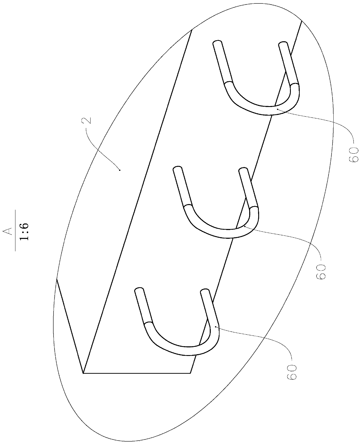
[0033] On the upper end of the web 4, there are a plurality of steel ba...


PUM


Abstract

The invention relates to a corrugated steel plate composite beam without an upper flange and a manufacturing method thereof, and belongs to the technical field of bridges. The corrugated steel plate composite beam comprises a prefabricated steel beam and a concrete bridge deck. The prefabricated steel beam comprises a web and a bottom plate which are fixedly connected to form an inverted-T-shapedstructure, the web is a corrugated steel plate with the groove length direction arranged in the vertical direction, and the bottom plate is a strip-shaped straight steel plate. A plurality of steel bar through holes are formed in the upper end part of the web plate at intervals along the length direction of the web plate; a plurality of shear nails embedded into the concrete bridge deck slab are welded on two side plate surfaces of the upper end part respectively; a steel bar ring with a main body part buried in the concrete bridge deck slab penetrates through the steel bar through holes, andtwo end parts of the steel bar ring extend out of the side plate surface of the concrete bridge deck slab to form lap joint steel bar sections in lap joint with the adjacent composite beams. Accordingto the corrugated steel plate composite beam, the structural strength can be ensured, meanwhile, the steel consumption is reduced, the cost is reduced, the construction process can be simplified, andthe corrugated steel plate composite beam can be widely applied to the bridge engineering field.

Description

technical field [0001] The invention relates to the technical field of bridges, in particular to a corrugated steel plate composite beam without an upper flange and a manufacturing method thereof. Background technique [0002] The use of steel structures in bridge construction is becoming more and more common, and is currently mainly used in the construction of long-span bridges. To achieve the purpose of reducing beam height, reducing self-weight and speeding up construction time, but the proportion of steel structures or steel-concrete composite structures used in the construction of small and medium-span bridges is still very low, mainly because of the cost ratio of steel structures or steel-concrete composite structures Concrete structures are generally taller. However, compared with concrete structures, steel structures are more environmentally friendly and green, and can be recycled after failure, and basically do not generate construction waste. [0003] In the stru...

Claims


Application Information

Patent Timeline
Patent Type & Authority Applications(China)
IPC IPC(8): E01D19/00E01D101/26
CPCE01D19/00E01D2101/268
Inventor 郭斌强叶建龙沈小雷余茂峰
Owner ZHEJIANG PROVINCIAL INST OF COMM PLANNING DESIGN & RES CO LTD
Why Eureka
Try Eureka