LED street lamp for park road lighting

A technology of LED street lamps and roads, applied in outdoor lighting, lighting devices, lighting and heating equipment, etc., can solve the problems of waste of electric energy, multiple costs, etc., and achieve the effect of improving water accumulation, simple structure, and high energy utilization rate

Active Publication Date: 2021-06-22
江西旺来科技有限公司
View PDF0 Cites 0 Cited by
  • Summary
  • Abstract
  • Description
  • Claims
  • Application Information

AI Technical Summary

Problems solved by technology

[0003] However, the traditional park lighting needs to be connected in parallel to ensure relative independence. This requires laying a complex circuit system underground in the park. In the process of use and maintenance, more costs need to be invested. At the same time, the existing street lights realize their timing switches through program control, which leads to the fact that even when there is no one in the park at night, the street lights will be in the lighting state. Waste is more serious

Method used


Image

  • LED street lamp for park road lighting
  • LED street lamp for park road lighting

Examples


Embodiment 1

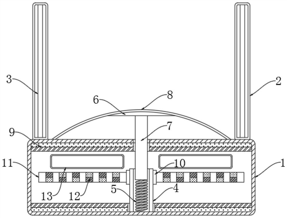
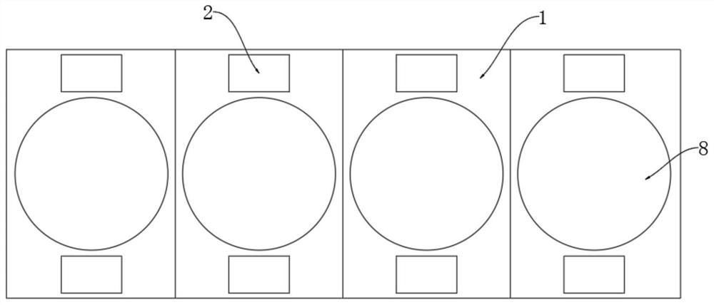
[0022] refer to Figure 1-2 , an LED street lamp for park road lighting, comprising a plurality of hollow brick bodies 1 laid on park roads and lampshades 2 fixedly connected to both sides of the brick body 1, a lamp body 3 is fixedly installed inside the lampshade 2, and inside the brick body 1 Both the bottom and the inner top are fixedly connected with a magnetic plate 9, and the inner bottom of the brick body 1 is rotatably connected with a sleeve 4, and a drive mechanism for driving the sleeve 4 to rotate is installed in the sleeve 4.

[0023] The drive mechanism includes a threaded rod 7 threaded in the sleeve 4. The upper end of the brick body 1 is fixedly connected with an arc-shaped protective cover 8. The lower end of the arc-shaped protective cover 8 is fitted with a pedal 6. The upper end of the threaded rod 7 extends to The outside of the brick body 1 is fixedly connected to the pedal 6. The lower end of the threaded rod 7 is elastically connected to the inner bot...

Embodiment 2

[0031] The difference from Embodiment 1 is that a storage battery coupled with the lamp body 3 and the excitation coil 13 is installed in the brick body 1, and a photosensitive switch coupled with the storage battery is installed in the lampshade 2, and the photosensitive switch controls whether the storage battery supplies power to the lamp body 3.

[0032] When the light is insufficient at night, the photosensitive switch is in the closed state. At this time, the excitation coil 13, the lamp body 3 and the storage battery form a closed loop. The battery is used to power the lamp body 3 to ensure that pedestrians have sufficient light conditions when walking on the park road;

[0033]When the light is sufficient during the day, the photosensitive switch is in an off state under the action of light. At this time, the battery does not supply power to the lamp body 3, and the excitation coil 13 only forms a closed circuit with the battery. When a pedestrian walks through the arc-...


PUM


Abstract

The invention discloses an LED street lamp for lighting park roads, which comprises a plurality of hollow brick bodies laid on park roads and lampshades fixedly connected to both sides of the brick bodies. Both the bottom and the inner top are fixedly connected with a magnetic plate, and the bottom of the brick body is rotatably connected with a sleeve, and a driving mechanism for driving the rotation of the sleeve is installed in the sleeve, and a drive mechanism for driving the sleeve is installed on the side wall of the sleeve. A power supply mechanism for supplying power to the lamp body. The present invention can convert the gravitational potential energy when pedestrians walk by into electric energy to supply power to the lamp body by setting the driving mechanism, power supply mechanism, battery and photosensitive switch, which not only does not need to lay complex circuit systems, reduces investment costs, but also only when pedestrians walk from the road The street lights will only emit light when passing by, which not only realizes the on-demand supply of electric energy, but also ensures the walking safety of pedestrians.

Description

technical field [0001] The invention relates to the technical field of LED street lamps, in particular to an LED street lamp for lighting park roads. Background technique [0002] LED lights are light-emitting diodes, which are lamps made of solid semiconductor chips as light-emitting materials. Compared with traditional lamps, LED lights have the advantages of energy saving, environmental protection, good color rendering and response speed, so LED lights are called the fourth Modern lighting sources or green light sources are widely used in various indications, displays, decorations, backlights, general lighting and urban night scenes. On the roads of urban parks, LED lights are also mostly used for lighting. [0003] However, the traditional park lighting needs to be connected in parallel to ensure relative independence. This requires laying a complex circuit system underground in the park. In the process of use and maintenance, more costs need to be invested. At the same...

Claims


Application Information

Patent Timeline
Patent Type & Authority Patents(China)
IPC IPC(8): F21S9/02F21S9/04F21V23/00F21V15/02F21V31/00F21V23/04F21V17/16F21W131/103F21Y115/10
CPCF21S9/02F21S9/04F21V15/02F21V17/162F21V23/003F21V23/0464F21V31/00F21W2131/103F21Y2115/10
Inventor 张翔
Owner 江西旺来科技有限公司
Why Eureka
Try Eureka