Multi-stage pipeline type hysteresis heat effect heating power generation method and generator

A thermal effect, pipeline-type technology, applied in the field of multi-stage pipeline-type hysteresis thermal effect heat generation and generator, can solve the problem of high electric power requirements, and achieve the effect of safe and fast cascade heating

Pending Publication Date: 2020-01-17
GUANGZHOU SUNTRANS MEASUREMENT & CONTROL SYST
View PDF0 Cites 5 Cited by
  • Summary
  • Abstract
  • Description
  • Claims
  • Application Information

AI Technical Summary

Problems solved by technology

[0006] Moreover, the existing steam generator has high requirements for electric power to meet its direct heating of a large-capacity water body, so that it must be controlled at a lower heating speed and pressure to ensure its heating safety

Method used


Image

  • Multi-stage pipeline type hysteresis heat effect heating power generation method and generator
  • Multi-stage pipeline type hysteresis heat effect heating power generation method and generator
  • Multi-stage pipeline type hysteresis heat effect heating power generation method and generator

Examples


Embodiment 1

[0077] The multi-stage pipe-type hysteresis thermal effect heat generator of this embodiment includes three-stage heating pipe assemblies.

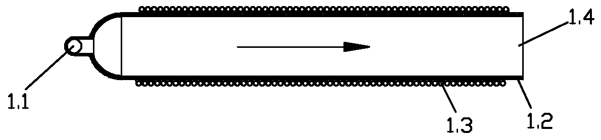
[0078] Such as figure 1 As shown, the heating tube assembly of this embodiment includes a first heating tube 1.2 and a first coil 1.3 sleeved on the first heating tube 1.2, the left end of the first heating tube 1.2 is provided with an inlet 1.1, and the right end is provided with an outlet 1.4, as shown in the figure The direction of the arrow indicates the direction of water flow. In this embodiment, the outer surface of the first heating tube 1.2 is provided with a magnetically sensitive metal material layer capable of generating hysteresis thermal effect in a changing magnetic field. When in use, an alternating magnetic field is generated by the first coil 1.3, and a hysteresis thermal effect occurs on the magnetic material layer to generate heat, which is transferred to the water body to be heated therein through the side wall of th...

Embodiment 2

[0082] The multi-stage pipe-type hysteresis thermal effect heat generator of this embodiment also includes three-stage heating pipe assemblies.

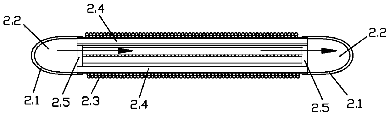
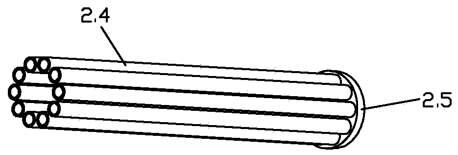
[0083] Such as figure 2 and image 3 As shown, the heating tube assembly of this embodiment includes a second coil 2.3, ten second heating tubes 2.4 and two ends 2.1, the end 2.1 is provided with a water collection chamber 2.2, and ten second heating tubes 2.4 are installed in two Between the ends 2.1, the two ends of the second heating pipe 2.4 communicate with the water collection cavity 2.2 in the ends 2.1 respectively. Specifically, the end 2.1 of this embodiment is an elbow, such as figure 2 As shown, the middle channel of the elbow is the water collection cavity 2.2, and the two ends of the ten second heating pipes 2.4 are respectively connected together through the circular cover plate 2.5, and the ten second heating pipes 2.4 are evenly distributed in the circumferential direction, and the second heating pipes The port o...

Embodiment 3

[0089] The multi-stage pipe-type hysteresis thermal effect heat generator of this embodiment also includes three-stage heating pipe assemblies.

[0090] Such as Figure 4 to Figure 10 As shown, the heating tube assembly 3 of this embodiment includes a third heating tube 3.3, a third coil 3.1, several heating rods 3.4, four guide baffles 3.2, two mounting seats 3.9, an inlet conduit 3.10, and an outlet conduit 3.7 and two sealing heads 3.5. Wherein, the mounting base 3.9 includes an upper clamping base 3.9.1 and a lower clamping base 3.9.2.

[0091] The material of the 3rd heating pipe 3.3 is materials such as high-temperature resistant Teflon or quartz, pottery, corundum, utilizes the water transmission property of materials such as Teflon, quartz and pottery, corundum to reduce the damping of water flow, can adapt to the damping of water flow simultaneously Under the action of a strong magnetic field, the activity of calcium and magnesium ions is enhanced to avoid the forma...


PUM


Abstract

The invention discloses a multi-stage pipeline type hysteresis heat effect heating power generation method and a generator. The heating power generation method includes the steps that at least two stages of heating pipe assemblies are arranged to form step heating, and the hysteresis heat effect occurs in a changing magnetic field through a magnetic sensitive metal material to generate heat to heat water or steam in a pipe; and the heating pipe assemblies are sequentially connected in series to form step heating. The heating power generator is provided with at least two stages of heating pipeassemblies, the heating pipe assemblies generate the changing magnetic field through a coil, the hysteresis heat effect occurs on the changing magnetic field through the magnetic sensitive metal material to generate the heat, and liquid or gas flowing in all stages of heating pipes is heated. The multiple stages of heating pipe assemblies are sequentially connected in series to form step heating,and the heating power generation method is realized through the heating pipe assemblies. According to the heating power generation method and the generator, high-temperature high-pressure liquid, steam or gas can be rapidly generated.

Description

technical field [0001] The present invention relates to a multi-stage pipeline type hysteresis heat effect heat generation method, and also relates to a generator adopting the above-mentioned multistage pipeline type hysteresis heat effect heat generation method. Background technique [0002] Steam generators are widely used in industry and life, and existing steam generators include resistive and eddy current. [0003] The core structure of the resistance steam generator is the structure of heating water through electric heating wire or resistance heating rod, which is a very traditional structure. Since the resistance heating body is in direct contact with the heated water body, the heating body and the heated water body The limitation of the contact surface area, especially the low efficiency of heat conduction, high energy consumption, and the incomplete isolation of water and electricity, the safety is poor. [0004] The core structure of the eddy current steam generat...

Claims


Application Information

Patent Timeline
Patent Type & Authority Applications(China)
IPC IPC(8): F22B1/28
CPCF22B1/281
Inventor 郑贵林郑力铭黄宗赵朱庆金梁健
Owner GUANGZHOU SUNTRANS MEASUREMENT & CONTROL SYST
Why Eureka
Try Eureka