Method for eliminating rigid displacement in airplane deformation under free flight trim load

A displacement and rigidity technology, applied in the field of accurate and efficient solution algorithms for real elastic displacements

Active Publication Date: 2020-01-17
NORTHWESTERN POLYTECHNICAL UNIV
View PDF9 Cites 5 Cited by
  • Summary
  • Abstract
  • Description
  • Claims
  • Application Information

AI Technical Summary

Problems solved by technology

[0004] The present invention aims at the above-mentioned deficiencies in the calculation of the elastic displacement of the static deformation of the aircraft under the action of the trim load in the free flight state, and proposes an accurate and efficient method for eliminating the overall rigid displacement of the structure

Method used


Image

  • Method for eliminating rigid displacement in airplane deformation under free flight trim load
  • Method for eliminating rigid displacement in airplane deformation under free flight trim load
  • Method for eliminating rigid displacement in airplane deformation under free flight trim load

Examples


Embodiment 1

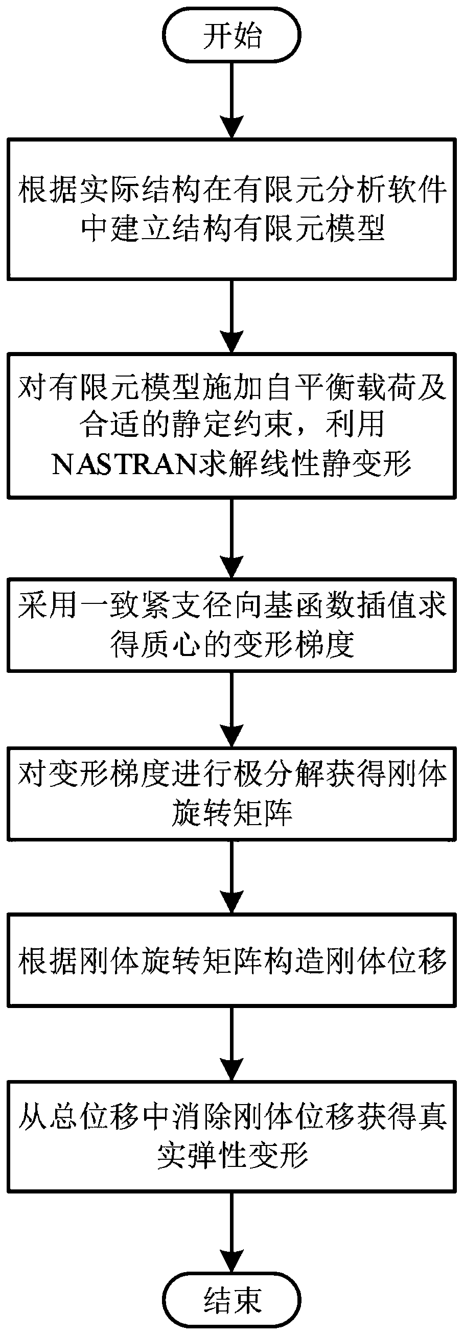
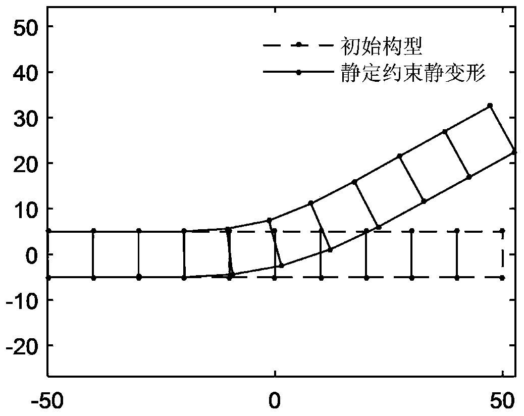
[0086] This embodiment is a process of eliminating rigid displacement for the static deformation of a two-dimensional plane beam subjected to self-balancing load. The specific process includes the following steps:

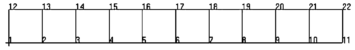
[0087] Step S11, establish a two-dimensional planar beam model in PATRAN, divide 10 grids in the length direction, and divide 1 grid in the height direction, and its model and finite element grid are as follows figure 2 As shown, the geometric dimensions and material parameters of the plane beam model are shown in Table 1.

[0088] Table 1 Plane beam geometry and material parameters

[0089]

[0090] Step S12, apply a vertical upward load of 1000N on node 3 and node 9, and apply a vertical downward load of 2000N on node 17, these applied loads form a self-balancing load system for the plane beam. Statically determinate constraints are applied to the left end of the planar beam, and the u and v directions of node 1 and the u direction displacement of node 12 a...

Embodiment 2

[0105] The above-mentioned embodiment 1 is an analysis of a simple plane beam. In order to verify the applicability of the algorithm of the present invention to a complex structure, the operation of a thin-walled UAV wing is described below. The specific process includes the following steps:

[0106] Step S21, using CATIA and Hypermesh software to model and mesh the CAD model of the wing of the drone. The geometric shape and internal skeleton structure of the UAV wing are as follows: Image 6 As shown, it can be divided into the central wing, the left and right outer wings, and the split points are A3L and A3R. The positions of the key points are marked in the figure. The model is symmetrical about the midplane A0-B0. Table 4 gives the size parameters of the right half wing, and its half span is 8900mm.

[0107] Table 4 Wing Plane Size Parameters

[0108]

[0109] Finite element mesh of UAV wing such as Figure 7 shown. In this calculation example, the finite element m...


PUM


Abstract

The invention discloses a method for eliminating rigid displacement in airplane deformation under a free flight trim load. Basic feature comprises: applying any reasonable statically determinate constraint to the structural finite element model with the balancing load effect; calculating to obtain structural displacement data by using engineering commercial software; reconstructing a displacementfield on a selected area by means of a consistent tight support radial basis interpolation function, constructing a deformation gradient matrix, performing extreme decomposition operation on the deformation gradient matrix to obtain a product of a symmetric matrix and an orthogonal matrix, the symmetric matrix describing the extension of the structure, and the orthogonal matrix reflecting the rotation of the structure; and according to the rigid rotation matrix obtained by the extreme decomposition, constructing the overall rigid displacement of the structure, and then eliminating the overallrigid displacement of the structure from the total displacement, so that the real elastic displacement of the free structure is obtained. According to the method, the basic characteristics of the total rigid matrix of the structure are not changed, the operand is small, the calculation is simple, and the overall rigid displacement of the structure caused by statically indeterminate constraint setting in the static deformation calculation process can be efficiently eliminated.

Description

technical field [0001] The present invention is applicable to the accurate and efficient solution algorithm of real elastic displacement under the action of trim load in the free flight state of the aircraft, and more specifically, for the aircraft under the action of trim load, combined with finite element analysis software, it can accurately and quickly eliminate the problems caused by static constraints. The overall rigid displacement of the structure is used to obtain the true elastic deformation of the free-flying state. Background technique [0002] Static linear elastic numerical analysis of engineering structures is the basic technical work of engineering design. In the analysis of actual engineering structures, free structures are often involved, that is, situations where constraints are insufficient or completely unconstrained, such as an airplane in a free-flying state. For an aircraft in a free-flying state, the aerodynamic load and mass inertial load it receive...

Claims


Application Information

Patent Timeline
Patent Type & Authority Applications(China)
IPC IPC(8): G06F30/15G06F30/23G06F17/16
CPCG06F17/16
Inventor 戎宇飞孙秦
Owner NORTHWESTERN POLYTECHNICAL UNIV
Why Eureka
Try Eureka