Check patentability & draft patents in minutes with Patsnap Eureka AI!

Mounting rack for large boring row, and quick installation method thereof

A mounting frame and boring row technology, applied in the field of mechanical processing, can solve the problems of fixed circular boring row safety hazards, equipment accidents and safety accident hazards, machine tool overload accidents, etc., so as to shorten auxiliary time, avoid equipment accidents, reduce Effects of equipment accidents

Inactive Publication Date: 2020-01-21
CSSC MES DIESEL
View PDF7 Cites 0 Cited by
  • Summary
  • Abstract
  • Description
  • Claims
  • Application Information

AI Technical Summary

Problems solved by technology

[0007] 1) Method 1: hoisting and direct installation, the hook needs to be very close to the machine tool, and there are also unstable factors in the sling, so there are hidden dangers of equipment accidents and safety accidents
[0008] 2) In the second method, since the boring row is completely fixed on the contour block during installation, and it is installed manually by personnel visually, it is easy to cause machine tool overload accidents caused by human misoperation, resulting in damage to the machine tool
[0009] 3) When using method 2 to install different shapes of boring rows, different installation methods must be used, the operation is more cumbersome, and there are still potential safety hazards when fixing circular boring rows

Method used


Image

  • Mounting rack for large boring row, and quick installation method thereof
  • Mounting rack for large boring row, and quick installation method thereof
  • Mounting rack for large boring row, and quick installation method thereof

Examples


Embodiment Construction

[0075] The installation frame and quick installation method for a large boring row according to the present invention will be further described in detail in conjunction with the accompanying drawings and specific embodiments.

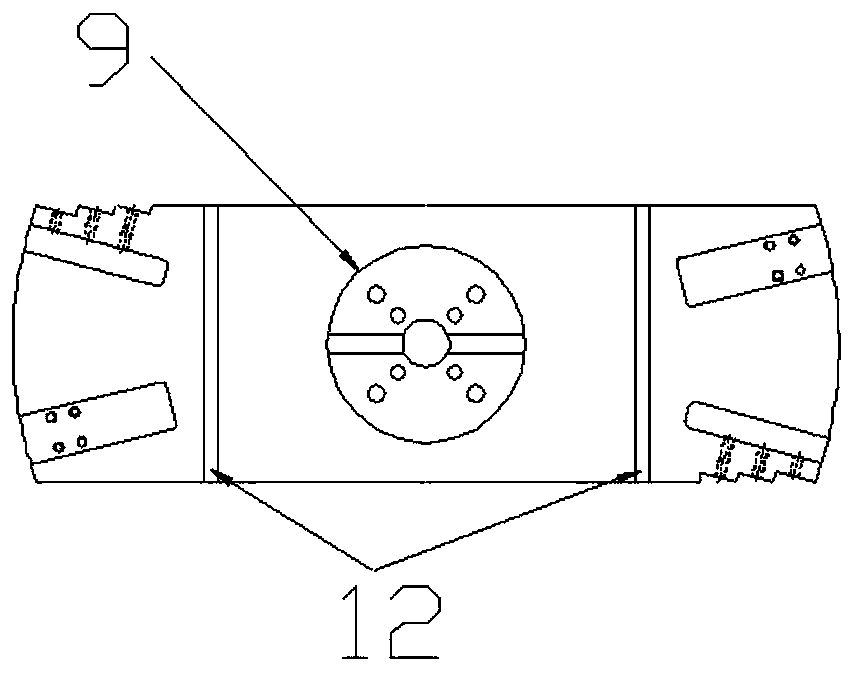
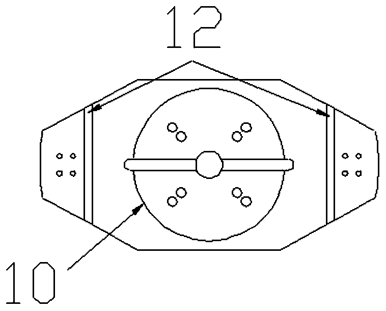
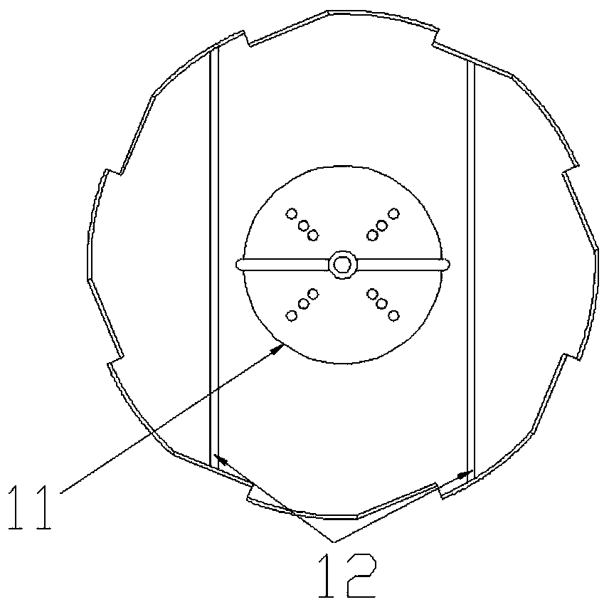
[0076] Please refer to Figure 4 , Figure 5 and Figure 6 , the installation frame of the present invention is fixed on the machine tool table, and mainly includes a base 1, a base 2, a left frame 3, a right frame 4, a top column assembly 5, two adjustable positioning support assemblies 6, and two rotating blocks Assembly 7 and a plurality of protective positioning support assemblies 8 .

[0077] The base 1 is fixed on the machine table; the base 2 rests on the base 1 . The left bracket 3, the right bracket 4, the top column assembly 5 and the two adjustable positioning support components 6 are fixed on the upper plane of the base 2, and the left bracket 3 and the right bracket 4 are respectively arranged on On both sides of the front part of the b...


PUM


Abstract

The invention discloses a mounting rack for a large boring row. The mounting rack for the large boring bow comprises a base, a pedestal, a left blocking rack, a right blocking rack, an ejection columnassembly, two adjustable positioning supporting assemblies, two rotary stop dog assemblies and a plurality of protection positioning supporting assemblies, wherein the base is fixed to a machine toolplatform surface, the pedestal is placed onto the base, the left blocking rack and the right blocking rack are arranged on the two sides of the front portion of the pedestal respectively, the ejection column assembly is arranged in the center of the rear portion of the pedestal, and is opposite to the left blocking rack and the right blocking rack in position, the two adjustable positioning supporting assemblies are arranged behind the left blocking rack and the right blocking rack respectively, the two rotary stop dog assemblies are connected to the outer side face of the left blocking rackand the outer side face of the right blocking rack respectively, and the multiple protection positioning supporting assemblies are fixed to the periphery of the outer side of the pedestal and are connected with the base. Because quick positioning installation of the boring row is achieved by utilizing a numerical control program, the mounting rack for the large boring row has the advantages of being quick to operate, and safe and reliable to use, has the beneficial effects that the labor intensity is reduced, the potential safety hazard is avoided, the machining efficiency is improved, and theproduct quality is guaranteed, and the mounting rack can be used for installing various of large boring rows.

Description

technical field [0001] The invention relates to a machine tool accessory, in particular to a mounting frame and a quick mounting method for a large boring row, and belongs to the technical field of mechanical processing. Background technique [0002] In the processing and manufacturing of high-power and low-speed marine diesel engines, many large-diameter holes are processed in the horizontal direction on CNC machine tools, such as crankshaft holes in the machine base, cylinder liner holes in cylinder blocks, through holes at both ends of connecting rods, etc. The processing of these holes has the following characteristics: 1. The hole diameter is large, generally between 680mm and 1300mm; 2. The cutting force is large, and the ordinary taper shank is Latin, and the vibration is obviously unable to cut; 3. The requirements for dimensional accuracy and roughness are relatively high. High, the dimensional accuracy requirements are generally between 0mm and 0.1mm. Therefore, i...

Claims


Application Information

Patent Timeline
Patent Type & Authority Applications(China)
IPC IPC(8): B23B29/24B23B29/00B23B21/00
CPCB23B29/00B23B29/24B23Q1/25
Inventor 金朝兵吴广宇顾亮沈治东
Owner CSSC MES DIESEL
Features
  • R&D
  • Intellectual Property
  • Life Sciences
  • Materials
  • Tech Scout
  • Unparalleled Data Quality
  • Higher Quality Content
  • 60% Fewer Hallucinations
Learn More