Cutting method of side leather material

A cutting method and edge leather technology, which are applied in the field of edge leather cutting, can solve the problems of long contact time and cutting time, and the cutting efficiency of sharp corners and curved convex parts needs to be improved, so as to reduce the slicing time and improve the Cutting efficiency, the effect of improving slicing efficiency

Pending Publication Date: 2020-01-21
CHANGZHOU SHICHUANG ENERGY CO LTD
View PDF5 Cites 10 Cited by
  • Summary
  • Abstract
  • Description
  • Claims
  • Application Information

AI Technical Summary

Problems solved by technology

The relative displacement between the diamond wire and the edge leather in the length direction of the edge leather, the contact time between the diamond wire and the edge leather (that is, the cutting time) is longer, and the cutting efficiency of the sharp corners and arc-shaped convex parts needs to be improved

Method used


Image

  • Cutting method of side leather material
  • Cutting method of side leather material
  • Cutting method of side leather material

Examples


Embodiment 1

[0050] Such as Figure 4 to Figure 6 As shown, the present invention provides a specific scheme of the above-mentioned trimming method, comprising the following specific steps:

[0051] A1) Cut off the edge leather: cut off the edge leather to obtain small pieces of edge leather;

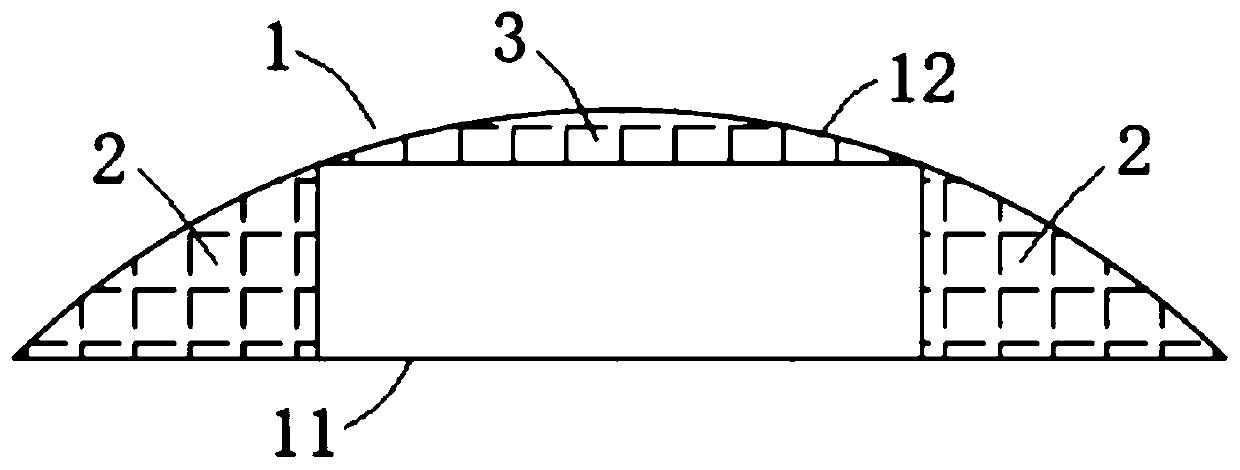
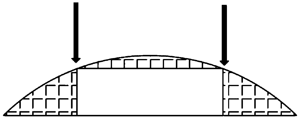
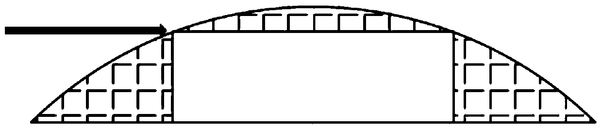
[0052] A2) Cut off the sharp corners and arc-shaped protrusions on both sides of the small leather section: Cut off the sharp corners on both sides of the small leather section along the thickness direction of the small leather section, and cut off the edges along the width direction of the bottom surface of the small leather section The arc-shaped convex part of the leather small section is obtained into a rectangular parallelepiped silicon block;

[0053] A3) Silicon block slicing: slice the silicon block along the direction parallel to the bottom surface of the silicon block to obtain single crystal silicon wafers.

[0054] The present invention provides a scheme of cutting first, then cutting ...

Embodiment 2

[0064] Such as Figure 7 to Figure 9 As shown, the present invention also provides another specific scheme of the above-mentioned trimming method, which includes the following specific steps:

[0065] B1) Cut off the sharp corners and arc-shaped protrusions on both sides of the edge leather: Cut off the sharp corners on both sides of the edge leather along the thickness direction of the edge leather, and cut off the arc of the edge leather along the width direction of the bottom surface of the edge leather Shaped convex part, get rectangular parallelepiped silicon block;

[0066] B2) Truncating the silicon block: truncating the silicon block to obtain a small section of the silicon block;

[0067] B3) Slicing of the small silicon block: Slicing the small silicon block in a direction parallel to the bottom surface of the small silicon block to obtain a single crystal silicon wafer.

[0068] The present invention also provides a scheme of cutting off sharp corners and arc-shap...


PUM

PropertyMeasurementUnit
lengthaaaaaaaaaa

Abstract

The invention discloses a cutting method of a side leather material. The side leather material is generated through silicon single crystal rod squaring. The side leather material comprises a rectangular bottom face, an arc face reverse to the bottom face, and a pair of end faces arranged on the two ends, in the length direction, of the bottom face; combination parts of the bottom face and the arcface are sharp corner portions; and the portion, between the sharp corner portions on the two sides of the side leather material, of the arc face is an arc protruding portion. The cutting method comprises the steps that the sharp corner portions on the two sides are cut off, and the arc protruding portion is cut off; and in the thickness direction of the side leather material, the sharp corner portions on the two sides are cut off, and the arc protruding portion is cut off in the width direction of the bottom face of the side leather material. The cutting time of the sharp corner portions andthe arc protruding portion can be reduced, the cutting efficiency of the sharp corner portions and the arc protruding portion can be improved, slicing time is shortened, and the slicing efficiency isimproved.

Description

technical field [0001] The invention relates to a cutting method of edge leather. Background technique [0002] Monocrystalline silicon wafers are cut from single crystal silicon rods. Generally, the single crystal silicon rods are first cut into squares to obtain cuboid silicon blocks whose length direction is consistent with the length direction of the silicon rods, and then the silicon blocks are sliced ​​into single crystal silicon wafers. [0003] The squaring of monocrystalline silicon ingots will produce side skins, and the side skins are generally returned to the furnace or used as high-efficiency polycrystalline ingot seed crystals, etc., resulting in a low utilization rate of monocrystalline silicon rods. [0004] Cutting the scrap material into silicon wafers can improve the utilization rate of monocrystalline silicon rods. [0005] The edge leather generally includes: a rectangular bottom surface, a curved surface opposite to the bottom surface, and a pair of en...

Claims


Application Information

Patent Timeline
Patent Type & Authority Applications(China)
IPC IPC(8): B28D5/04
CPCB28D5/04B28D5/045
Inventor 孟祥熙曹育红符黎明
Owner CHANGZHOU SHICHUANG ENERGY CO LTD
Why Eureka
Try Eureka