An electronically controlled power device with real-time controllable thrust and repeatable ignition and flameout

A technology of repeated ignition and power plant, applied in rocket engine, jet propulsion, machine/engine, etc., can solve the problems of limited energy supply, limited effect, accelerated burning speed, etc., achieve rapid installation and disassembly, and reduce contact area , to avoid the effect of taking up too much space

Active Publication Date: 2022-04-08
NANJING UNIV OF SCI & TECH
View PDF6 Cites 1 Cited by
  • Summary
  • Abstract
  • Description
  • Claims
  • Application Information

AI Technical Summary

Problems solved by technology

However, there are two major defects in the popularization and application of solid propellant engines: on the one hand, after the solid propellant is extinguished, it is difficult to ignite again, and multiple starts cannot be achieved; on the other hand, the combustion process of solid propellant is uncontrolled, making it difficult to achieve Thrust adjustment
The above-mentioned improvement methods all belong to the passive adaptation to the combustion characteristics of solid propellants, the effect is limited, and it is still impossible to achieve multiple starts and flexible thrust adjustment
[0004] Although the currently available electronically controlled solid propellants meet the above requirements, during the combustion process of the grain, due to changes in temperature and the length of the grain itself, the resistance of the grain itself changes, so that the burning rate at the same voltage is accelerated, and it cannot produce all the propellants. Need constant thrust
As an exception, due to the limited external energy supply that can be carried on missile weapons, reducing energy consumption in the process of realizing the above requirements is also a severe problem faced by missile weapon power plants at present

Method used


Image

  • An electronically controlled power device with real-time controllable thrust and repeatable ignition and flameout
  • An electronically controlled power device with real-time controllable thrust and repeatable ignition and flameout
  • An electronically controlled power device with real-time controllable thrust and repeatable ignition and flameout

Examples


Embodiment Construction

[0027] Below in conjunction with accompanying drawing, the present invention will be further described

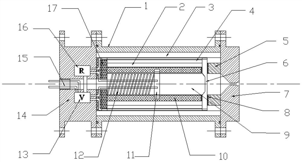
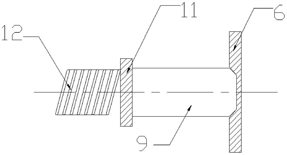
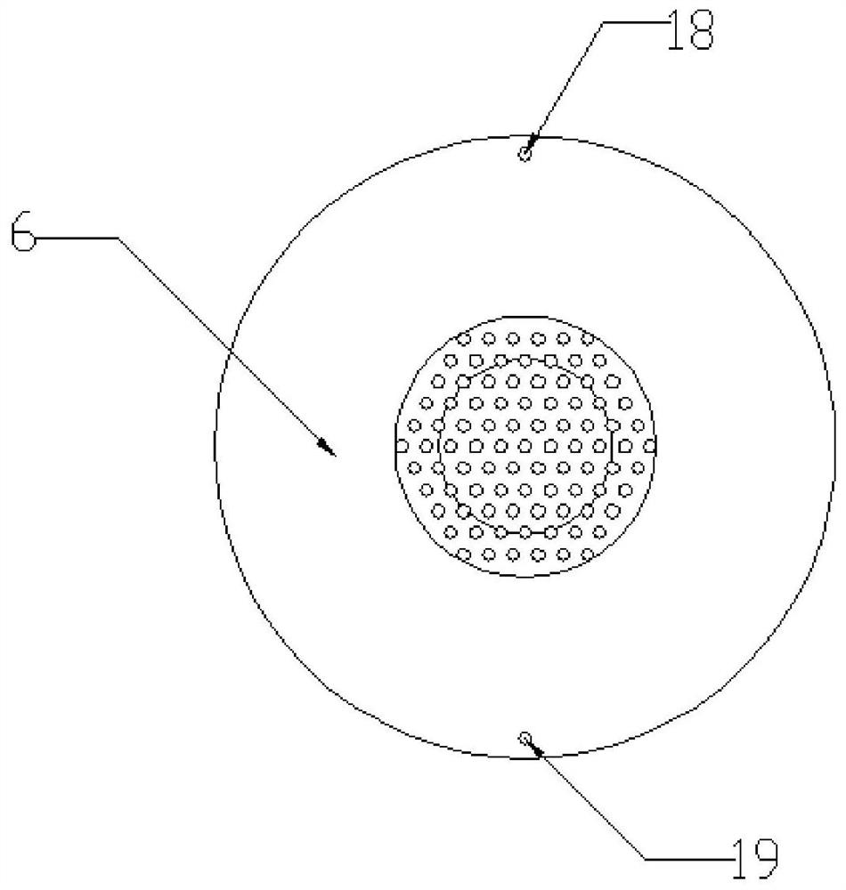
[0028] Such as figure 1 As shown, the present invention includes a combustion chamber housing 1, a corundum insulating layer 2, a silicon rubber insulating layer 3, a heat protection layer 4, an electrode fixing sleeve 5, a combustion surface electrode 6, a nozzle 7, an asbestos gasket 8, an electric control solid Propellant grain 9, electrode fixing device 10, sliding electrode 11, spring 12, voltage controller 13, fixed sealing end 14, electrode pin 15, resistance monitor 16 and lead terminal insulating plate 17. The electronically controlled solid propellant grain 9 is installed in the combustion chamber housing 1, the front end of the electrically controlled solid propellant grain 9 is in contact with the combustion surface electrode 6, and the rear end is in contact with the sliding electrode 11, and the spring 12 pushes the sliding electrode 11 and The electrically c...


PUM


Abstract

The invention discloses an electronically controlled power device with real-time controllable thrust and repeatable ignition and extinguishment, which includes a combustion chamber shell, a nozzle, an electrode fixing sleeve, an electrode, an electrically controlled solid propellant grain, a spring, and insulation for lead terminals. Plates, electrode fixtures, thermal shields, insulation, resistance monitors, voltage controllers, stationary seals, and electrode pins. The device of the present invention reduces the voltage required for the first ignition by changing the initial burning surface of the propellant grain and the electrode structure of the burning surface, and at the same time, the layer electrode contact and the end surface combustion mode ensure that the same end surface can burn stably; through the resistance monitor and voltage control Cooperate with the device, adjust the applied voltage, and ensure a certain amount of thrust; use the electrode pins to cooperate with the fixed sealing end, which can not only seal the combustion chamber, but also be easy to assemble with external missiles or aircraft to achieve rapid installation and disassembly. Purpose.

Description

technical field [0001] The invention relates to the field of special solid motors, in particular to an electronically controlled power device with real-time controllable thrust and repeatable ignition and flameout. Background technique [0002] In order to meet the needs of high mobility, fast response, and high interception capability of missiles in future wars, missile weapons and equipment are developing in the direction of high mobility and rapid defense penetration, requiring missile engines to be capable of repeated multiple starts and real-time controllable thrust. Although the liquid rocket engine can achieve multiple ignitions, its complex structure, toxic propellant and long filling time do not meet the needs of rapid response operations. The solid rocket motor has a simple structure and short launch preparation time, and is more suitable as a missile weapon power device. However, there are two major defects in the popularization and application of solid propellan...

Claims


Application Information

Patent Timeline
Patent Type & Authority Patents(China)
IPC IPC(8): F02K9/26F02K9/24F02K9/32F02K9/34F02K9/94
CPCF02K9/26F02K9/34F02K9/32F02K9/24F02K9/94
Inventor 张伟鲍立荣沈瑞琪叶迎华
Owner NANJING UNIV OF SCI & TECH
Why Eureka
Try Eureka