A gradient transition type anti-icing full heat recovery core and its working method

A technology of total heat recovery and heat recovery core, which is applied in the field of total heat recovery core and gradual transitional anti-icing total heat recovery core, which can solve the problems that the core area cannot be effectively used for heat exchange and moisture transfer, etc. To achieve the effect of flexible and convenient use, change of area, and high heat transfer efficiency

Active Publication Date: 2021-04-20
SUZHOU HUILIN ENERGY SAVING MATERIALS CO LTD
View PDF8 Cites 0 Cited by
  • Summary
  • Abstract
  • Description
  • Claims
  • Application Information

AI Technical Summary

Problems solved by technology

[0004] The root cause of this situation is that no matter how large the core configuration is, the cross flow of the air flow can not effectively use the area of ​​the core due to the heat exchange and moisture transfer.

Method used


Image

  • A gradient transition type anti-icing full heat recovery core and its working method
  • A gradient transition type anti-icing full heat recovery core and its working method
  • A gradient transition type anti-icing full heat recovery core and its working method

Examples


Embodiment 1

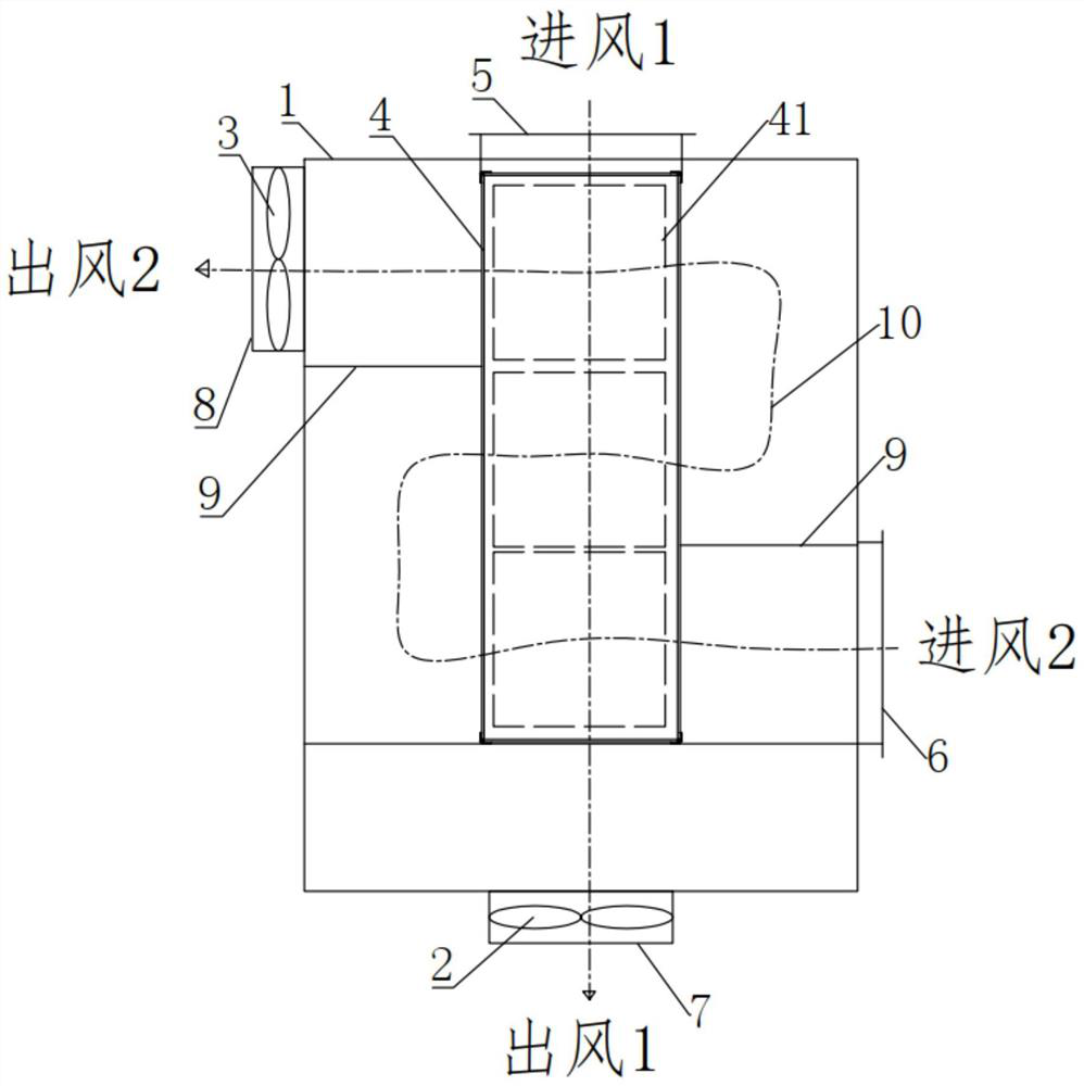
[0041] Such as image 3 The gradual and transitional anti-icing total heat recovery core body shown includes an outer casing 1, fan 1 2, fan 2 3, heat recovery unit 4, air inlet 1 5, air inlet 2 6, air outlet 1 7 and outlet Air outlet two 8, the heat recovery unit 4 is arranged in the outer casing 1, and the heat recovery unit 4 is located in the middle of the outer casing 1, the air inlet one 5, the air inlet two 6, the air outlet one 7 and the air outlet two 8 are all arranged on the outer wall of the outer casing 1, the air inlet-5 and the air outlet-7 are arranged facing each other, the two ends of the heat recovery unit 4 communicate with the air inlet-5 and the air outlet-7 respectively, the The air inlet one 5 and the air outlet two 8 are located on the same side of the outer casing 1, the air inlet two 6 and the air outlet one 7 are located on the other side of the outer casing 1 away from the air inlet one 5, and the fan one 2 is arranged at the air outlet One 7, the...

Embodiment 2

[0053] Such as Figure 5 The outer walls of the cold fin frame 415 and the hot fin frame 417 are provided with extension plates 20, and the ends of both sides of the extension plate 20 are provided with fin distance adjustment assemblies 30, and the cold fin frame 415 The fin distance adjustment assembly 30 on the frame 417 is connected to a set of cold fins 414 , and the fin distance adjustment assembly 30 on the heat fin frame 417 is connected to a set of heat fins 416 .

[0054] Such as Figure 6-8 The fin distance adjustment assembly 30 shown includes a telescopic cylinder 301, a fixed base 302, a linear optical axis 1 303, a linear optical axis 2 304, a set of upper spacing adjustment blocks 305 and a set of lower spacing adjustment blocks 306. The seat 302 is fixedly arranged on the upper end surface of the extension plate 20, the telescopic cylinder 301 is fixedly arranged on the fixed base 302, and the piston rod of the telescopic cylinder 301 passes through the fixed...


PUM


Abstract

The invention discloses a gradual and transitional anti-icing total heat recovery core body, which comprises an outer casing, a fan 1, a fan 2, a heat recovery unit, an air inlet 1, an air inlet 2, an air outlet 1 and an air outlet 2. A group of partition plates are arranged between the two side walls of the heat recovery unit and the inner wall of the outer casing, and the group of partition plates forms a folded air flow channel inside the outer cover shell, and the two ends of the folded air flow channel are respectively In communication with the air inlet 2 and the air outlet 2, the heat recovery unit includes a set of heat recovery cores, and the air entering the air inlet 2 passes through a set of heat recovery cores sequentially along the reentrant airflow channel. The gradual transitional anti-icing total heat recovery core of the present invention, 1) The flow of air in the heat exchange core (the area inside each dotted line box) will not cause excessive temperature and humidity differences on both sides In this area, the gradual transition of temperature and humidity is realized. This flow is closer to counterflow in terms of the total heat transfer temperature difference, and the heat transfer efficiency is also greater.

Description

technical field [0001] The invention belongs to the technical field of fresh air systems, and in particular relates to a gradual and transitional anti-icing full heat recovery core body. The invention also relates to a working method of a gradual transition anti-icing full heat recovery core body. Background technique [0002] The plate-fin total heat recovery core is a commonly used device. The wind usually flows in the direction of x and y channels to realize the exchange of temperature and humidity in the air flow, thereby realizing energy recovery. [0003] At present, the recycled cores used in the market are usually square. In some extreme cases, such as in winter bathhouses in northern my country, such as figure 1 , 2 When the outdoor cold air (inlet 1) and the indoor high-humidity warm air (intake 2) are energy recovered, the temperature at A is the lowest, and the moisture in the high-humidity warm air (intake 2) does not have time to diffuse to the cold air ( In...

Claims


Application Information

Patent Timeline
Patent Type & Authority Patents(China)
IPC IPC(8): F24F12/00F28D9/00F28F3/00
CPCF24F12/001F28D9/00F28F3/00Y02B30/56
Inventor 陈磊秦革仲华
Owner SUZHOU HUILIN ENERGY SAVING MATERIALS CO LTD
Why Eureka
Try Eureka