Cylindrical battery module cooling system and battery module

A cylindrical battery and cooling system technology, applied in battery pack components, secondary batteries, circuits, etc., can solve the problems of battery pack weight gain, unfavorable automated production, complex battery module structure, etc., to improve cycle life, Ensuring uniform temperature and consistency

Pending Publication Date: 2020-01-21
LINKDATA NEW ENERGY CO LTD
View PDF2 Cites 4 Cited by
  • Summary
  • Abstract
  • Description
  • Claims
  • Application Information

AI Technical Summary

Problems solved by technology

The disadvantage of this solution is that the structure of the battery module is complex, and it is difficult to ensure consistency during mass production, which is not conducive to automated production
The disadvantage of this solution is that although aluminum is a light metal, the use of multiple brackets will significantly increase the weight of the battery pack; second, the commonly used insulation treatmen

Method used


Image

  • Cylindrical battery module cooling system and battery module
  • Cylindrical battery module cooling system and battery module
  • Cylindrical battery module cooling system and battery module

Examples


Embodiment 1

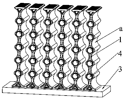
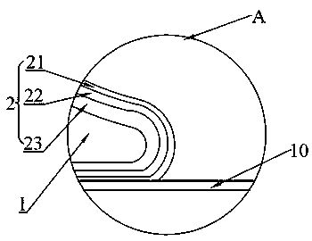
[0040] Such as Figure 1-2 As shown, the cylindrical battery module cooling system in Embodiment 1 includes a first insulating support 1, a heat conduction layer 2 and a heat exchange plate 3, and a cell matching groove a is provided on the cell contact surface of the first insulating support 1, and the first The heat exchange end surface of the insulating support 1 is in contact with the heat exchange plate 3; the heat conduction layer 2 is coated on the cell contact surface and the heat exchange end surface of the first insulating support 1; the heat conduction layer 2 includes an insulating surface layer 21, a graphite film 22 and an elastic Buffer layer 23.

[0041] The first insulating bracket 1 is provided with a weight-reducing through hole 4 that is axially aligned with the cell matching groove a.

[0042] The material of the first insulating support 1 is polycarbonate.

[0043] The material of the elastic buffer layer is foam, and the thickness of the elastic buffer...

Embodiment 2

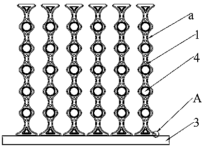
[0047] Such as Figure 3-4As shown, embodiment 2 is based on embodiment 1, the difference is that embodiment 2 also includes a second insulating support 5 with the following structure: one side of the second insulating support 5 is provided with a cell matching groove a, and the other side is a plane . The number of cells in the assembled battery module is N, the number of insulating supports is N+1, and the arrangement is followed by the second insulating support 5, N-1 first insulating supports 1, and the second insulating supports 5. That is, the planar side of the second insulating support 5 is the surface of the battery module.

Embodiment 3

[0049] Such as Figure 5 As shown, the battery module of Example 3 includes the cylindrical battery module cooling system of Example 1, and also includes a battery cell 6, a first module bracket 7 and a second module bracket 8, and the first module bracket 7 and The second module support 8 is provided with a recessed portion 9, and the first insulating support 1 is provided with a protrusion that matches the recessed portion 9, and the protrusion on the first insulating support 1 includes a through hole 4 communicated with The protruding ring b and the V-shaped protrusion c located at both ends of the insulating support.


PUM

PropertyMeasurementUnit
Thicknessaaaaaaaaaa
Thicknessaaaaaaaaaa

Abstract

The invention discloses a cylindrical battery module cooling system, and the system comprises an insulating bracket, a heat conduction layer and a heat exchange plate; a battery cell matching groove is formed in a battery cell contact surface of the insulating bracket, and a heat exchange end surface of the insulating bracket is in contact with the heat exchange plate; the heat conduction layer coats the battery cell contact surface and the heat exchange end surface of the insulating bracket; the heat conduction layer comprises an insulation surface layer, a graphite film and an elastic bufferlayer. The cylindrical battery module cooling system takes an insulating bracket as a support, a battery cell contact surface and a heat exchange end surface of the insulating bracket are provided with a heat conduction layer comprising an insulating layer, a graphite film and an elastic buffer layer, and a battery cell, the heat conduction layer and a heat exchange plate are combined to form aneffective solid-solid contact heat conduction structure. The invention also discloses a battery module.

Description

technical field [0001] The invention relates to the technical field of lithium battery production, in particular to a cylindrical battery module cooling system and the battery module. Background technique [0002] The heat dissipation performance and temperature uniformity performance of the battery pack have a great influence on the reliability, cycle life and charge and discharge performance of the battery system, modules and cells. The main heat dissipation structures of cylindrical battery modules in the prior art are liquid cooling and aluminum cooling. [0003] Liquid cooling refers to serpentine tubes with serial or parallel passages between the cells, as described in CN106972218A, including cooling passages distributed on both sides of the battery pack with circulating cooling medium inside, and the battery pack generates The heat is transferred to the heat pipe, channel body and cooling medium in turn. The disadvantage of this solution is that the structure of the...

Claims


Application Information

Patent Timeline
IPC IPC(8): H01M10/613H01M10/643H01M10/6551H01M10/653H01M10/6554H01M10/6567H01M10/6561H01M10/658H01M2/10
CPCH01M10/613H01M10/643H01M10/653H01M10/6551H01M10/6554H01M10/6561H01M10/6567H01M10/658H01M50/20H01M50/213Y02E60/10
Inventor 薛从文王勒言张培侯宏伟
Owner LINKDATA NEW ENERGY CO LTD
Why Eureka
Try Eureka