
An equivalent circuit of a metamaterial unit and its feeding structure for an encoded metamaterial antenna

A metamaterial and antenna technology, applied in the field of metamaterials, can solve the problems of high loss and low efficiency, and achieve the effect of improving overall performance and total radiation efficiency

Active Publication Date: 2021-01-29
NAT UNIV OF DEFENSE TECH
View PDF9 Cites 0 Cited by
  • Summary
  • Abstract
  • Description
  • Claims
  • Application Information

AI Technical Summary

Problems solved by technology

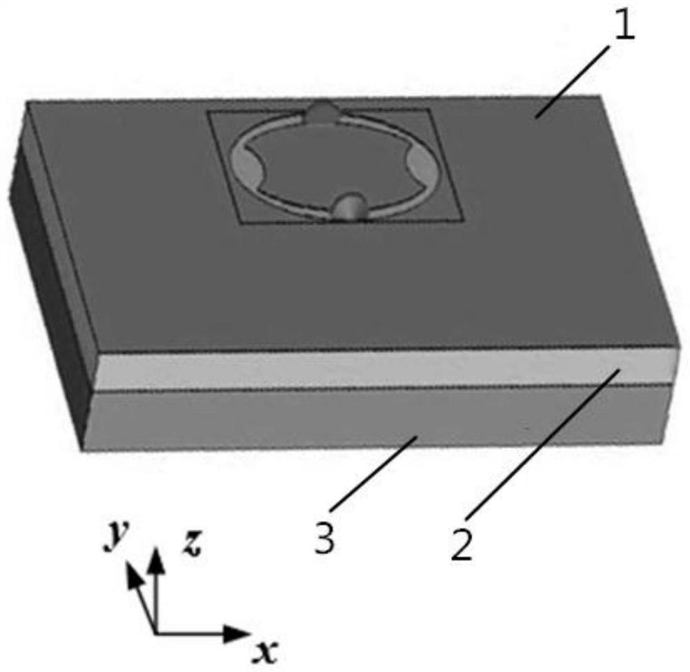
[0006] The purpose of the present invention is to provide a new type of metamaterial unit, which solves the problems of large loss and low efficiency of the traditional metamaterial unit used for encoding metamaterial antennas

Method used


Image

  • An equivalent circuit of a metamaterial unit and its feeding structure for an encoded metamaterial antenna
  • An equivalent circuit of a metamaterial unit and its feeding structure for an encoded metamaterial antenna
  • An equivalent circuit of a metamaterial unit and its feeding structure for an encoded metamaterial antenna

Examples


Embodiment 1

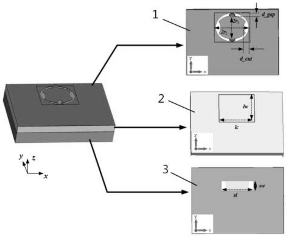
[0042] as attached Figure 1-Figure 2 and Image 6 A metamaterial unit used for encoding metamaterial antennas is shown, including a resonant unit 1, a back cavity 2 and a transmission line structure 3 stacked sequentially from top to bottom. For the convenience of installation, the resonant unit 1, the back cavity 2 and the The transmission line structure 3 is designed to be parallel to each other and all have a plate structure, wherein:

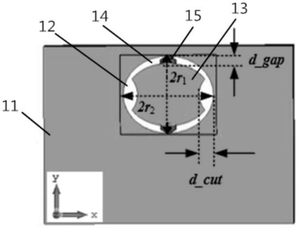
[0043] like image 3The resonant unit 1 shown includes a resonant substrate 11, the middle part of the resonant substrate 11 is provided with an escape groove 12 penetrating through the thickness direction, and a sheet conductor 13 is arranged in the avoidance groove 12, and the sheet conductor 13 and the A connection gap 14 is formed between the resonant substrates 11, and two diodes 15 are symmetrically arranged at both ends of the short axis of the avoidance groove 12 in the connection gap 14, and the positive and negative poles of the...

Embodiment 2

[0060] like Figure 6-7 A kind of equivalent circuit that is used for coding metamaterial antenna feed structure shown, comprises resistance 4, inductance 5 and is used for the metamaterial unit of coding metamaterial antenna as described in embodiment one; Said resistance 4, use The metamaterial unit and the inductance 5 of the coding metamaterial antenna are connected in series successively. When the diode 15 is disconnected, the equivalent circuit is composed of a resistor 4, an inductance 5 and a group of capacitors connected in series, and a group of capacitors is a sheet conductor 13 connected to The gap 14 and the diode 15 are connected in parallel; when the diode 15 is turned on, the equivalent circuit is composed of the resistor 4 and the inductor 5 in series.


PUM


Abstract

The invention discloses a metamaterial unit for encoding a metamaterial antenna, which includes a resonant unit, a back cavity and a transmission line structure; the resonant unit includes a resonant substrate, and the middle part of the resonant substrate is provided with an escape slot through which a sheet conductor is arranged inside , a connection gap is formed between the sheet conductor and the resonant substrate, and two diodes are arranged in the connection gap; the back cavity includes the back cavity substrate, and a rectangular groove is opened in the middle of the back cavity substrate, and the four inner walls of the rectangular groove are attached respectively. There is a metal film; a transmission line structure, including a waveguide substrate, and a waveguide slot is opened in the middle of the metal layer. The guided traveling wave of the present invention enters from the waveguide gap of the transmission line structure, realizes the indirect feed to the resonance unit through the coupling effect of the back cavity, directly isolates the current path of the transmission line structure and the resonance unit, and then suppresses the current flowing through the diode and reduces the The ohmic loss when the diode is turned on is reduced, thereby improving the overall performance of the metamaterial unit for encoding the metamaterial antenna.

Description

technical field [0001] The invention belongs to the technical field of metamaterials, in particular to a metamaterial unit used for encoding a metamaterial antenna. Background technique [0002] Metamaterial technology is a cutting-edge interdisciplinary technology, and its technical fields include electromagnetic, microwave, terahertz, photonics, advanced engineering design system, communication, semiconductor and other fields. Compared with the phased array antenna of the phase-shifting network, the metamaterial antenna using the metamaterial unit greatly reduces the system complexity, volume weight and cost, and has important application value. Since its radiation performance is directly determined by the radiation performance of metamaterial elements, the study of metamaterial elements with excellent performance is of great significance for better research on metamaterial antennas. [0003] The structure of the metamaterial unit currently used for encoding metamaterial ...

Claims


Application Information

Patent Timeline
Patent Type & Authority Patents(China)
IPC IPC(8): H01Q1/36H01Q1/50H01P3/00H01P7/00
CPCH01P3/00H01P7/00H01Q1/36H01Q1/50
Inventor 林铭团邓博文黄贤俊刘培国
Owner NAT UNIV OF DEFENSE TECH
Learn More