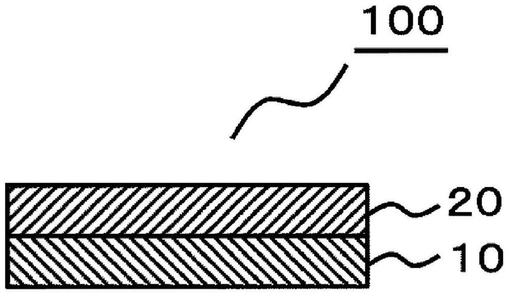
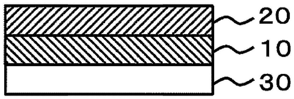
optical stack

A technology of optical laminates and absorbing layers, applied in optics, optical components, nonlinear optics, etc., can solve the problems of reduced brightness, high cost, abnormal hue, etc., and achieve the effects of sufficient brightness, suppressed reflectivity, and good hue

Active Publication Date: 2022-03-15
NITTO DENKO CORP
View PDF23 Cites 0 Cited by
  • Summary
  • Abstract
  • Description
  • Claims
  • Application Information

AI Technical Summary

Problems solved by technology

[0004] However, when polarizers are used, there are problems such as decreased brightness, abnormal hue, and high cost.

Method used


Image

  • optical stack
  • optical stack
  • optical stack

Examples


Embodiment 1

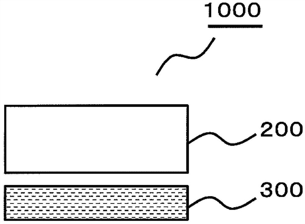
[0147] (wavelength conversion layer)

[0148] A commercially available TV (manufactured by Samsung, trade name "UN65JS9000FXZA") was disassembled to obtain a quantum dot sheet which is a wavelength conversion material contained on the backlight side. This quantum dot sheet is used as the wavelength conversion layer (1).

[0149] (absorbent layer)

[0150] Contains 0.3 wt. Parts, 1 part by weight of isocyanate crosslinking agent (manufactured by Tosoh, trade name "Coronate L"), 0.3 parts by weight of pigment (manufactured by Yamada Chemical Industry Co., Ltd., trade name "FDG-007"), phenolic antioxidant ( BASF Japan company make, brand name "IRGANOX1010") 0.2 weight part, and the pigment-containing adhesive was manufactured. The pigment-containing adhesive obtained above was applied with an applicator to a thickness of 20 μm on a PET substrate (manufactured by Mitsubishi Plastics Corporation, trade name "MRF38CK") subjected to a treatment to make the adhesive easy to peel, a...

Embodiment 2

[0154] (absorbent layer)

[0155] 0.3 parts by weight of the pigment used (manufactured by Yamada Chemical Industry Co., Ltd., trade name "FDG-007") was changed to 0.3 parts by weight of pigment (manufactured by Yamada Chemical Industry Co., Ltd., trade name "FDG-004"). Otherwise, the absorbing layer (2) was formed on TAC in the same manner as in Example 1. In addition, the dye used (manufactured by Yamada Chemical Industry Co., Ltd., trade name "FDG-004") is a compound having an absorption peak at a wavelength of 600 nm.

[0156] (optical laminate)

[0157] The wavelength conversion layer (1) obtained in Example 1 and the above-mentioned absorption layer (2) were laminated to obtain an optical laminate (2) having a laminated structure of a wavelength conversion layer / absorption layer. The results are shown in Table 1.

Embodiment 3

[0159] (absorbent layer)

[0160] 0.3 parts by weight of the pigment used (manufactured by Yamada Chemical Industry Co., Ltd., trade name "FDG-007") was changed to 0.3 parts by weight of pigment (manufactured by Yamada Chemical Industry Co., Ltd., trade name "FS-1531"). Otherwise, the absorbing layer (3) was formed on TAC in the same manner as in Example 1. In addition, the dye used (manufactured by Yamada Chemical Industry Co., Ltd., trade name "FS-1531") is a compound having an absorption peak at a wavelength of 700 nm.

[0161] (optical laminate)

[0162] The wavelength conversion layer (1) obtained in Example 1 and the above-mentioned absorption layer (3) were laminated to obtain an optical laminate (3) having a laminated structure of a wavelength conversion layer / absorption layer. The results are shown in Table 1.


PUM

PropertyMeasurementUnit
thicknessaaaaaaaaaa
thicknessaaaaaaaaaa
thicknessaaaaaaaaaa

Abstract

To provide an optical laminate capable of exhibiting sufficient luminance and good hue while suppressing reflectance when used in an image display device, thereby achieving cost reduction. The optical laminate of the present invention has a wavelength conversion layer that does not have a polarizing plate on the opposite side of the wavelength conversion layer when viewed from the absorption layer, and the wavelength conversion layer is a layer that converts part of the wavelength of incident light and emits light, The absorption layer is a layer containing a compound having an absorption peak between 480nm to 780nm wavelength, and the average reflectance R1 of the wavelength conversion layer at a wavelength of 380nm to 480nm is the same as the average reflectance R1 of the wavelength conversion layer at a wavelength of 490nm to 600nm The relationship of R2 is R2>R1, and the maximum peak value of the reflectance of the absorbing layer side of the optical laminate at a wavelength of 380 nm to 480 nm is P1, and the absorbing layer side of the optical laminate is at a wavelength of 490 nm to 600 nm. When the maximum peak value of the lower reflectance is P2, P2 / P1 is 0.7 to 1.5.

Description

technical field [0001] The present invention relates to optical laminates Background technique [0002] In recent years, an image display device including a light-emitting layer made of a light-emitting material such as quantum dots has attracted attention as an image display device excellent in color reproducibility (for example, Patent Document 1). For example, when light is incident on a quantum dot film using quantum dots, the quantum dots are excited to emit fluorescence. For example, when a blue LED backlight is used, part of the blue light passes through the quantum dot film and is converted into red light and green light, while part of the blue light is directly emitted in the form of blue light. As a result, white light can be realized. And it is generally believed that the use of such a quantum dot film can achieve a color reproducibility of NTSC ratio of 100% or more. [0003] The image display device as described above has a high reflectance. Therefore, in or...

Claims


Application Information

Patent Timeline
Patent Type & Authority Patents(China)
IPC IPC(8): G02B5/20G02B5/22G02F1/1335G02F1/13357
CPCG02B5/20G02B5/22G02F1/1335B32B7/023
Inventor 中村恒三吉川贵博池田哲朗
Owner NITTO DENKO CORP
Why Eureka
Try Eureka