Casting processing equipment and processing technology

A technology for processing equipment and castings, applied in the field of casting processing equipment and processing technology, can solve the problems of slow cooling speed of castings and reduced casting efficiency, and achieve the effects of improving cooling efficiency, ensuring cooling speed and high stability

Active Publication Date: 2020-12-25
济南平阴天宫铸造有限公司
View PDF1 Cites 0 Cited by
  • Summary
  • Abstract
  • Description
  • Claims
  • Application Information

AI Technical Summary

Problems solved by technology

[0004] The above-mentioned existing technical solutions have the following defects: in the casting process of the above-mentioned castings, natural cooling is used after pouring, so that the cooling speed of the castings is relatively slow, and the casting efficiency is greatly reduced

Method used


Image

  • Casting processing equipment and processing technology
  • Casting processing equipment and processing technology
  • Casting processing equipment and processing technology

Examples


Embodiment 1

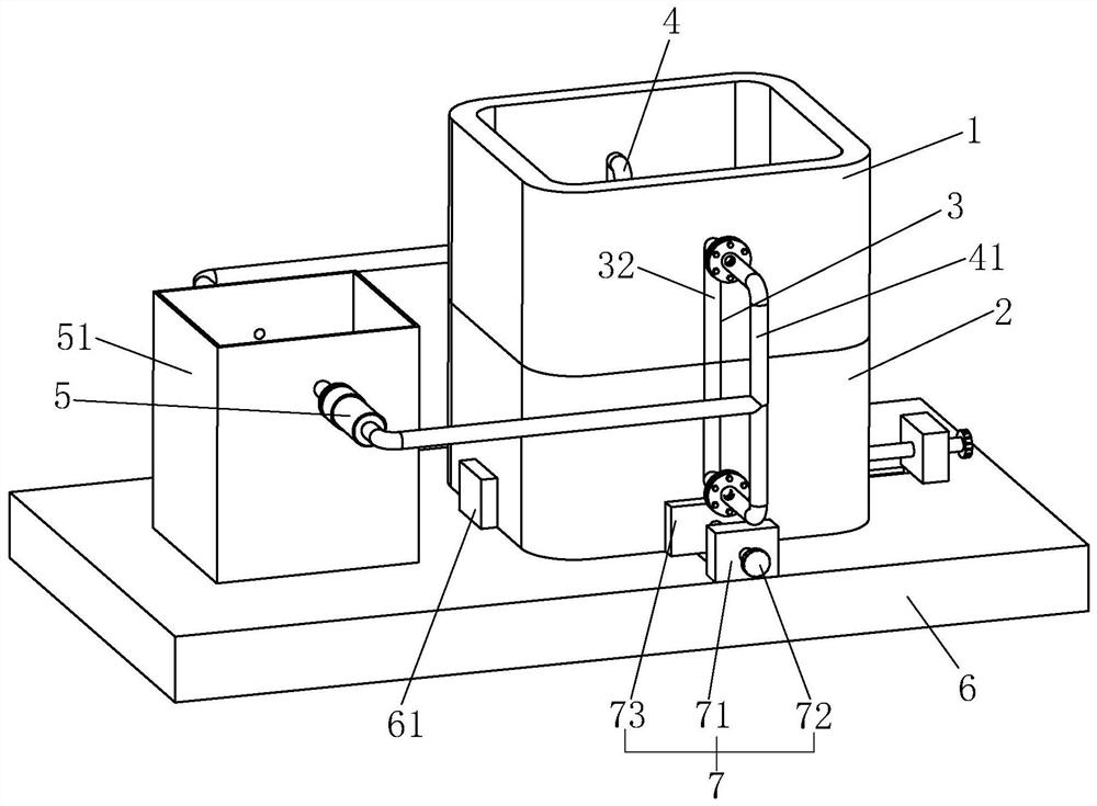
[0037] A casting processing equipment, such as figure 1As shown, including the upper shell type 1 and the lower shell type 2 stacked up and down, the upper shell type 1 and the lower shell type 2 are both vertically connected, and the bottom of the lower shell type 2 is placed with a horizontal bottom plate 6. During casting, Fill the area surrounded by the upper shell mold 1 and the lower shell mold 2 with the molding sand, and cover the mold with the molding sand. After compacting the molding sand, open the sprue and air passage on the top of the molding sand, and then separate the upper shell mold 1 and the lower shell Type 2, the mold cavity is formed after the mold is taken out, and the casting is cast by the runner to form the casting. The upper shell type 1 and the lower shell type 2 are equipped with cooling components around the cavity to accelerate the cooling of the casting, thereby improving the quality of the casting. manufacturing efficiency.

[0038] Such as ...

Embodiment 2

[0046] A casting process, comprising the steps of:

[0047] S1. Configure molding sand. The molding sand is made by mixing raw sand, clay, water, vegetable oil and sawdust, and the mixing ratios of raw sand, clay, water, vegetable oil and sawdust are 73%, 10%, 8%, 4%, and 5%, respectively. %;

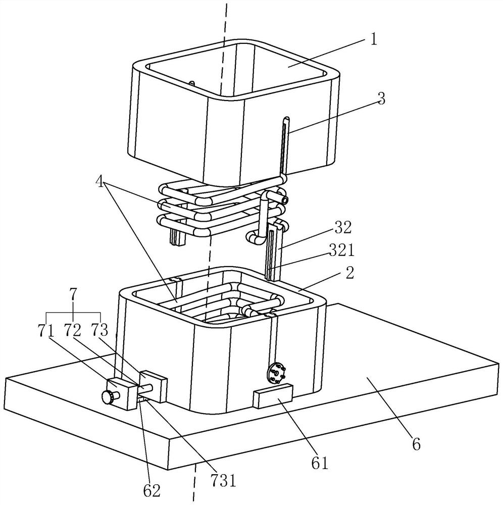
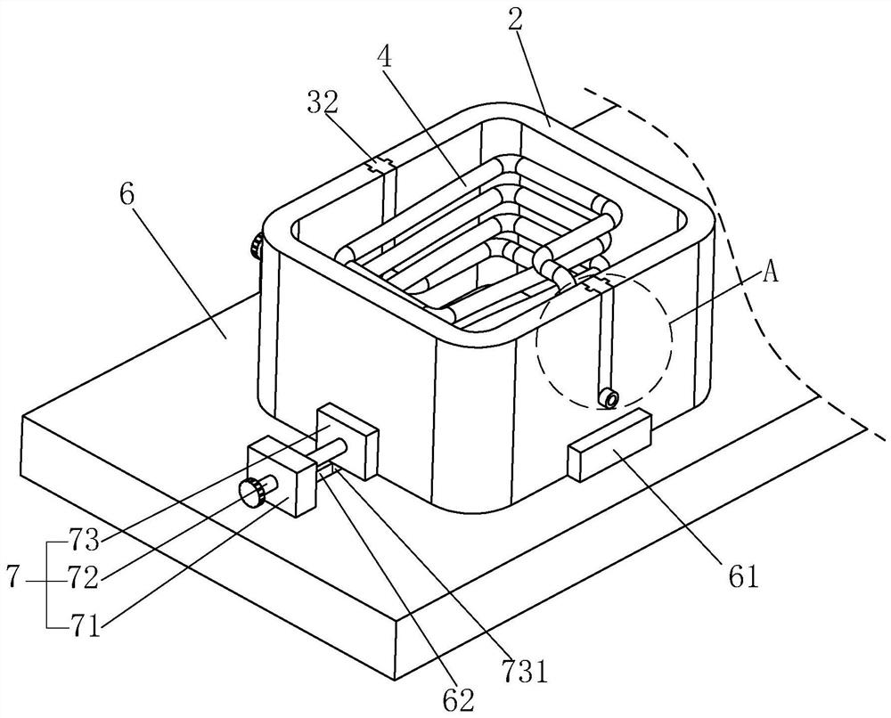
[0048] S2. Install the lower shell type 2, contact the two sides of the lower shell type 2 with the reference plate 61, turn the lead screw 72, and the lead screw 72 drives the clamping plate 73 to abut against the outer surface of the lower shell type 2;

[0049] S3. Fill one-third of the molding sand into the lower shell type 2, then put the mold prefabricated in advance into the lower shell type 2, and put the cooling pipe 4 into the lower shell type 2, so that the mold is located in the cooling pipe 4 In the annular area of ​​the shell, continue to fill the molding sand in the lower shell type 2 until it is filled;

[0050] S4. Stack the upper shell type 1 on the top of the lower ...


PUM


Abstract

The invention relates to casting machining equipment and a machining process, and belongs to the technical field of casting. The casting machining equipment comprises an upper shell mold and a lower shell mold aligned up and down; the upper shell mold and the lower shell mold are filled with molding sand; mounting grooves are formed in two opposite sides of the upper shell mold and two opposite sides of the lower shell mold; cooling pipes are inserted in the mounting grooves; the cooling pipes are vertically spiral in corresponding areas of the upper shell mold and the lower shell mold, and are embedded in the molding sand; the cooling pipes communicate with a water pump and a water tank for providing cooling water; and the casting machining equipment accelerates the cooling of castings toachieve the effect of improving the casting efficiency.

Description

technical field [0001] The invention relates to the technical field of casting, in particular to casting processing equipment and processing technology. Background technique [0002] Casting is the process of pouring smelted metal liquid into the mold, cooling and solidifying to obtain parts with the required shape and performance. Casting is a commonly used manufacturing method with low manufacturing cost and high process flexibility. It can obtain complex shapes and large castings, and it occupies a large proportion in mechanical manufacturing. [0003] The existing Chinese patent with the notification number CN106623806B can be referred to, which discloses a casting casting process, including the following steps: step S1, shell mold production, using refractory mud coated sand combined with shell molds to make the upper half shell mold and the lower shell mold. Half-shell type; step S2, shell type fitting, the upper half-shell type and the lower half-shell type are fitte...

Claims


Application Information

Patent Timeline
Patent Type & Authority Patents(China)
IPC IPC(8): B22C9/02B22C21/02B22D27/04B22C1/02B22C1/18
CPCB22C1/02B22C1/181B22C9/02B22C21/02B22D27/04
Inventor 胡雷于化军孙会平李永国董春兰尹燕义孙飞
Owner 济南平阴天宫铸造有限公司
Why Eureka
Try Eureka