
Active starting circuit of Boost full-bridge isolation converter and method

A technology of isolating converters and starting circuits, which is applied in the direction of converting DC power input to DC power output, instruments, electrical components, etc., can solve the problems of large inrush current of input inductance, inability to release inductive energy, and breakdown of power switch tubes, etc. Achieve the effect of reducing current impact, reducing flyback winding design, and smooth start

Inactive Publication Date: 2020-01-24
INST OF ELECTRICAL ENG CHINESE ACAD OF SCI
View PDF3 Cites 0 Cited by
  • Summary
  • Abstract
  • Description
  • Claims
  • Application Information

AI Technical Summary

Problems solved by technology

[0002] When the Boost full-bridge isolated converter starts, the output capacitor has no initial voltage. If it works directly in Boost mode, the duty cycle of the control circuit is at the maximum state. When the power switches are all turned on, the power supply voltage is added to the energy storage inductor. The current increases; when the switch tube is turned off, because the output voltage is very low and the power supply voltage is greater than the converted value of the transformer primary side of the output voltage, the current in the inductor continues to increase, that is, the energy stored in the inductor continues to accumulate and cannot be maintained within a cycle balance, the circuit will continue to charge the inductance, and the output voltage at this time is very low. After several cycles, the inductance energy cannot be released and will soon be saturated
If no measures are taken, the inrush current of the input inductor will be very large when starting, and even the power switch tube will be broken down.

Method used


Image

  • Active starting circuit of Boost full-bridge isolation converter and method
  • Active starting circuit of Boost full-bridge isolation converter and method
  • Active starting circuit of Boost full-bridge isolation converter and method

Examples


Embodiment Construction

[0021] The present invention will be further described below in conjunction with the accompanying drawings and specific embodiments.

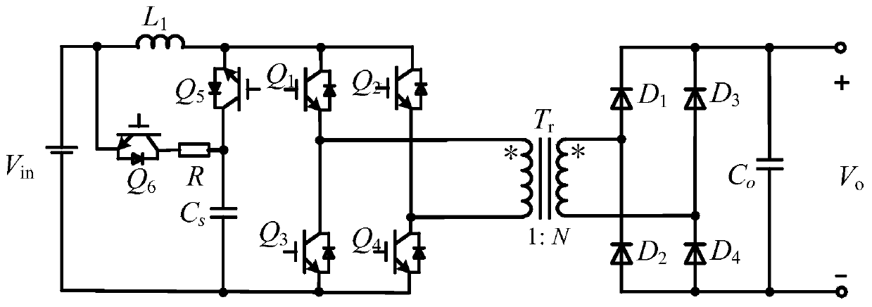
[0022] Such as figure 1 As shown, the present invention consists of an active switch Q6 and a resistor R to form a low-loss active start-up circuit; the present invention consists of a switching device Q5 and a clamping capacitor Cs to form an active clamping circuit, which is directly connected in parallel to the DC bus; the switching device Q1- Q4 forms a full-bridge power circuit, inductor L acts as a boost inductor, rectifier diodes D1-D4 form a high-frequency full-bridge rectifier circuit, and Co is an output filter capacitor.

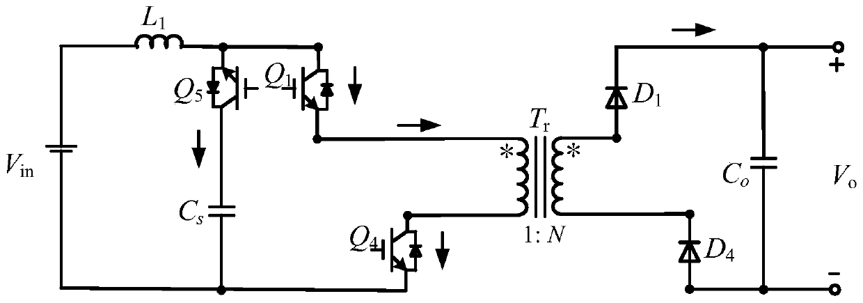
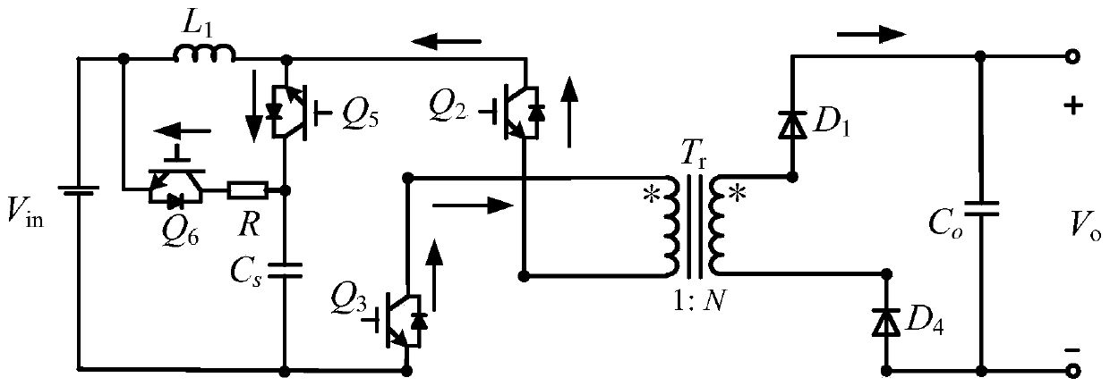
[0023] Such as Figure 4 As shown, the start-up process of the present invention has two working modes. Working mode 0 is that the switching devices Q1 and Q4 of the converter are turned on or Q2 and Q3 are turned on, and Q6 and Q5 are turned off. In this mode, the converter transmits to the secondary side of the ...


PUM


Abstract

The invention relates to an active starting circuit of a Boost full-bridge isolation converter and a method. An active switch Q6 and a resistor R constitute a low-loss active starting circuit of the circuit. In the starting process of the converter, the active starting circuit releases energy stored in a boost inductor by turning on the switching device Q6, the problem of inductor energy saturation in the starting process of the converter is thus solved, and the converter can be normally started. The switching device Q6 in the active starting circuit only works in the starting state of the converter. When the converter works in a working steady state, the switching device Q6 is turned off, and the conversion efficiency of the circuit will not be influenced.

Description

technical field [0001] The invention relates to the field of power electronics, in particular to a full-bridge isolated step-up DC conversion circuit and method. Background technique [0002] When the Boost full-bridge isolated converter starts, the output capacitor has no initial voltage. If it works directly in Boost mode, the duty cycle of the control circuit is at the maximum state. When the power switches are all turned on, the power supply voltage is added to the energy storage inductor. The current increases; when the switch tube is turned off, because the output voltage is very low and the power supply voltage is greater than the converted value of the transformer primary side of the output voltage, the current in the inductor continues to increase, that is, the energy stored in the inductor continues to accumulate and cannot be maintained within a cycle Balanced, the circuit will continue to charge the inductance, and the output voltage at this time is very low. Aft...

Claims


Application Information

Patent Timeline
Patent Type & Authority Applications(China)
IPC IPC(8): H02M1/36H02M3/335
CPCH02M1/36H02M3/33569
Inventor 魏苗苗王环卢俊龙由弘扬王一波
Owner INST OF ELECTRICAL ENG CHINESE ACAD OF SCI
Learn More