Method for filling vertical surface area on back edge of wind power blade

A filling method and area filling technology, which can be applied to other household appliances, household appliances, household components, etc., can solve the problems of narrow and flat cavity structure, hanging glass fiber cloth in the shell, and easy wrinkling of bonding corners. Simple and reasonable design, eliminate resin-rich defects, and improve the effect of bonding strength

Pending Publication Date: 2020-01-31
国能联合动力技术(保定)有限公司
View PDF0 Cites 3 Cited by
  • Summary
  • Abstract
  • Description
  • Claims
  • Application Information

AI Technical Summary

Problems solved by technology

If glass fiber cloth is used to fill this area, on the one hand, it will be difficult to layer and pour, and defects such as wrinkles and dry fibers will easily appear, which will affect the bonding quality and production efficiency; on the other hand, it will easily lead to problems such as overweight of the blade and change the mechanical properties of the trailing edge of the blade
If the bonding angle is made, due to the narrow and flat cavity structure and the small space, on the one hand, the manufacturing process is more complicated and it is not easy to form, on the other hand, the bonding angle is easy to wrinkle and collapse, requiring rework
[0004] At the same time, this area is a groove on the mold, and the glass fiber cloth of the shell is prone to be suspended when laying layers. After vacuum infusion, a rich resin will be formed, which will reduce the mechanical properties of the blade and affect the strength and service life of the blade.

Method used


Image

  • Method for filling vertical surface area on back edge of wind power blade

Examples


Embodiment Construction

[0020] In order to better understand the purpose, structure and function of the present invention, a method for filling the elevation area of ​​the trailing edge of a wind turbine blade according to the present invention will be further described in detail below in conjunction with the accompanying drawings.

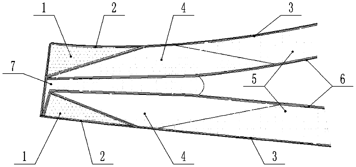
[0021] Such as figure 1 As shown, it is shown as a method for filling the trailing edge elevation area of ​​a wind power blade according to the present invention, which is used to adjust the mold clamping gap in the trailing edge elevation area of ​​the blade. The filling method includes:

[0022] First, before laying the shell outer skin 3, the cladding layer 2 is laid on the corresponding position of the rear edge elevation of the shell on the SS surface and / or the PS surface.

[0023] Specifically, the coating layer 2 is two layers of biaxial cloth, which is laid on the surface of the mold groove at the elevation of the trailing edge of the blade, and covers the cushi...


PUM


Abstract

The invention discloses a method for filling a vertical surface area on a back edge of a wind power blade. The method comprises the following steps: before paving outer skin of a shell, paving coatinglayers to corresponding positions of vertical surfaces on the back edges of shells of an SS surface and a PS surface; paving a plurality of cushion blocks in a die groove, filling the back edge groove and attaching the vertical surface of the die groove tightly; successively paving the outer skin of the shell, single-direction cloth, a core material of the shell and inner skin of the shell to pave the whole shell; paving an auxiliary material, and carrying out vacuum pouring, pre-curing, auxiliary material cleaning, trial closing and die assembling glue scratching steps; and overturning to assemble the die, and bonding and fixing the SS surface shell and the PP surface shell together by means of the die assembling glue. The method is simple and reasonable in structural design, convenientto operate and high in production efficiency, avoids a phenomenon that glass fiber cloth in the position is suspended during layer pavement, eliminates a resin enriched defect, and improves the bladequality. A die assembling gap in the vertical surface area on the back edge of the blade is adjusted effectively, a thickness overproof problem of the area is eliminated, and the bonding strength is improved.

Description

technical field [0001] The invention relates to the field of wind power blade structures, in particular to a method for filling the elevation area of ​​a trailing edge of a wind power blade. Background technique [0002] The middle part of the trailing edge of the wind turbine blade is a facade with a certain thickness, which is embodied as a groove on the mold. In this area, the internal cavity clearance of the blade is relatively large, and some positions exceed the theoretical clamping clearance. The mold clamping gap is an important indicator that directly affects the shape of the outer contour of the blade, the amount of mold clamping glue, and the weight of the blade. If the mold clamping gap is too large, the thickness of the mold clamping glue will be out of tolerance and the bonding strength will be reduced. This requires precise control of the blade mold clamping gap. [0003] In order to adjust the clamping gap here, glass fiber cloth is generally used to fill or...

Claims


Application Information

Patent Timeline
Patent Type & Authority Applications(China)
IPC IPC(8): B29C70/34B29C70/44B29C70/54B29L31/08
CPCB29C70/342B29C70/443B29C70/541B29C70/542B29L2031/085
Inventor 刘梅刘广李江波赵亚男姜宏业杨潺覃盛琼
Owner 国能联合动力技术(保定)有限公司
Why Eureka
Try Eureka