Wetting device for textile cloth

A technology for textile fabrics and textile fabrics, applied in the field of wetting devices for textile fabrics, which can solve problems such as increased production costs, production impacts, health hazards of employees, etc., and achieve the effects of ensuring cleanliness, easy collection, and easy cleaning

Inactive Publication Date: 2020-01-31
张林
View PDF2 Cites 14 Cited by
  • Summary
  • Abstract
  • Description
  • Claims
  • Application Information

AI Technical Summary

Problems solved by technology

[0005] 1. When the brush is used to clean the dust on the surface of the textile cloth, the cleaned dust is not recycled, so that the dust will float in the air and cause harm to the health of employees;
[0006] 2. Use a humidity detector to detect the wetness of the surface of the textile cloth. After the detection is unqualified, the textile cloth is wet again.

Method used


Image

  • Wetting device for textile cloth
  • Wetting device for textile cloth
  • Wetting device for textile cloth

Examples


Embodiment 1

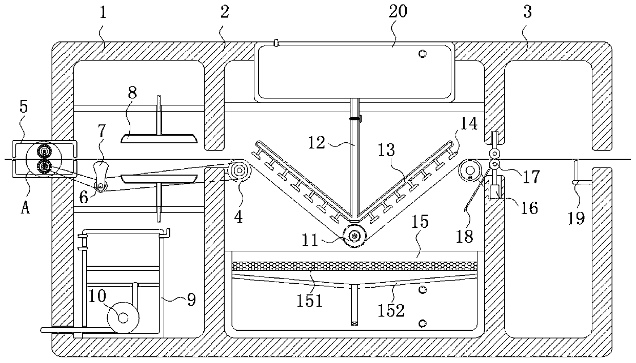
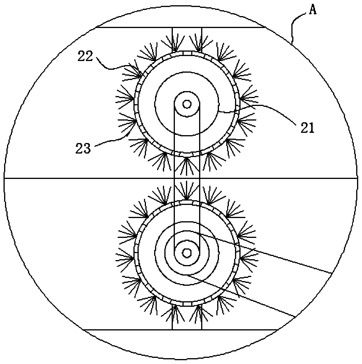
[0033] refer to Figure 1-4 , a wetting device for textile cloth, including a box body composed of a dust removal chamber 1, a humidification chamber 2 and a detection chamber 3, and the inner walls between two adjacent chambers are provided with frame openings for the passage of textile cloth, The inwall of detection chamber 3 is equipped with humidity detection device 19, and humidity detection device 19 is prior art, can determine whether the degree of humidity in the textile cloth meets the requirements, and the relative inwall of wetting chamber 2 is positioned at the lower side of frame mouth and is all rotatably connected with The outer wall of the roller 4 and the wetting chamber 2 is fixedly connected with a driving motor 33 for driving the rotation of the roller 4, and the relative inner wall of the wetting chamber 2 is fixedly connected with a water-absorbing cylinder 11, and the lower end of the water-absorbing cylinder 11 is evenly distributed with water-absorbing ...

Embodiment 2

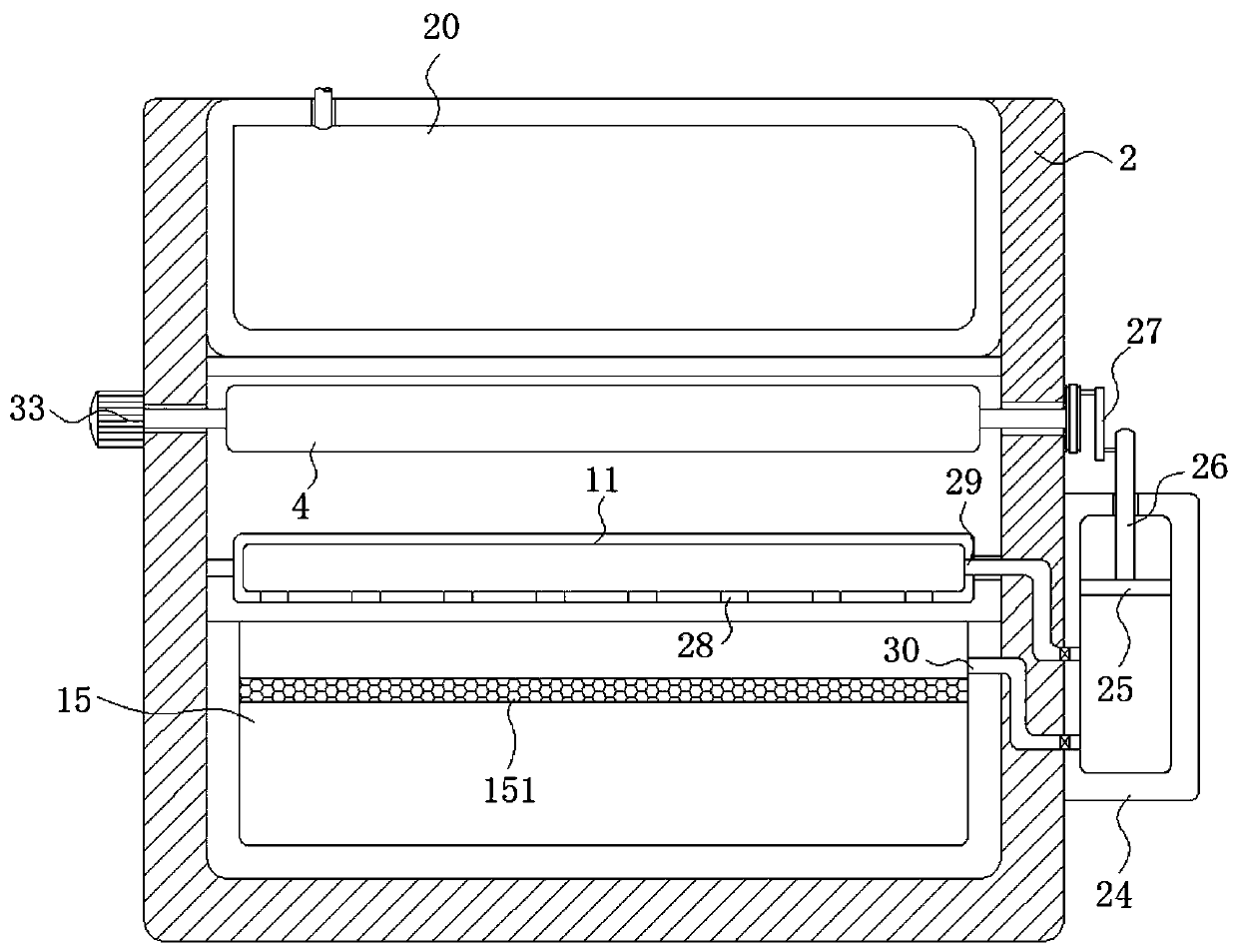
[0042] refer to Figure 5 , different from Embodiment 1, the inner wall of the waste water collection tank 15 is located below the filter screen 151 and is provided with a conical plate 152. A one-way valve with water flowing from top to bottom. It should be noted that this one-way valve adopts the DIF-L10H1 type one-way valve. The opening pressure of this one-way valve is 0.04MPa, and the lower end of the hollow pipe is close to the waste water. The inner bottom of the collection tank 15 allows water to accumulate at the highest height on the hollow tube and the conical plate 152. From the pressure formula: p=ρgh, it can be seen that the vertical height of water accumulated on the one-way valve only needs to be greater than 0.4m. Just can make one-way valve open, thereby makes waste water flow in the waste water collecting tank 15 through one-way valve after being filtered, and the joint of vertical bar 26 and slide plug barrel 24 is provided with sealing ring, and the upper ...


PUM


Abstract

The invention discloses a wetting device for textile cloth. The wetting device comprises a cabinet. The cabinet comprises a dust removal chamber, a wetting chamber and a detection chamber. Frame openings for allowing the textile cloth to pass through are formed in inner walls of every two adjacent chambers. A cleaning device for cleaning dust on the surface of the textile cloth is mounted in the dust removal chamber, and a squeezing device for squeezing excessive moisture on the textile cloth is mounted on the side wall of the frame opening between the wetting chamber and the detection chamber. The wetting device has the advantages that a dust suction pipe communicated with a rotating joint can adsorb and collect dust on bristles, thereby preventing the dust from being scattered in the air; water in a waste water collection tank can enter a water storage tank again through a sliding plug cylinder on the side wall of the wetting chamber, and accordingly, water resources are saved; the wettability of the textile cloth can be controlled through a squeezing roller on an electric push rod, and accordingly, the situation that water spraying is needed after the wettability of the textilecloth is detected to be unqualified is avoided.

Description

technical field [0001] The invention relates to the technical field of textile machinery and equipment, in particular to a wetting device for textile cloth. Background technique [0002] Humidity conditions are closely related to the textile process. The textile industry uses fiber raw materials. Under different humidity conditions, their physical and mechanical properties will change to varying degrees. For example, cotton fiber, at a relative humidity of 60%-70 %, the tensile strength of the fiber can be increased by about 50% compared with the dry state. This is because the moisture-absorbed cotton fiber, due to the increase in the distance between molecules, will produce relative displacement under the action of external force, so the elongation of the fiber increases with the The relative humidity increases, so before the production of the textile fabric, it is necessary to moisten the textile fabric to enhance the elongation of the textile fabric, which is beneficial t...

Claims


Application Information

Patent Timeline
IPC IPC(8): D06B1/02D06B15/02D06B23/20D06G1/00B08B15/04
CPCB08B15/04D06B1/02D06B15/02D06B23/20D06G1/00
Inventor 张林魏兰
Owner 张林
Why Eureka
Try Eureka