Method for planning laser scanning path of thin-walled part and 3D printing method

A technology of laser scanning path and thin-walled parts, which is applied in the field of additive manufacturing, can solve problems such as unevenness and over-thickness of the blank, and achieve the effect of improving flatness, reducing the thickness of the blank, and meeting the requirements of machining allowance

Inactive Publication Date: 2020-02-04
TSC LASER TECH DEV BEIJING CO LTD
View PDF5 Cites 6 Cited by
  • Summary
  • Abstract
  • Description
  • Claims
  • Application Information

AI Technical Summary

Problems solved by technology

[0003] In order to solve the problems of excessive thickness and uneven allowance of thin-walled parts produced by 3D printing in the prior art, a laser scanning path planning method and 3D printing method for thin-walled parts are provided.

Method used


Image

  • Method for planning laser scanning path of thin-walled part and 3D printing method
  • Method for planning laser scanning path of thin-walled part and 3D printing method
  • Method for planning laser scanning path of thin-walled part and 3D printing method

Examples


Embodiment 1

[0063] A laser scanning path planning method for thin-walled parts, comprising the following steps:

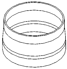
[0064] S1. Establish a three-dimensional model of the thin-walled part to be formed, and divide the three-dimensional model into several slice layers. Slicing layers such as image 3 shown.

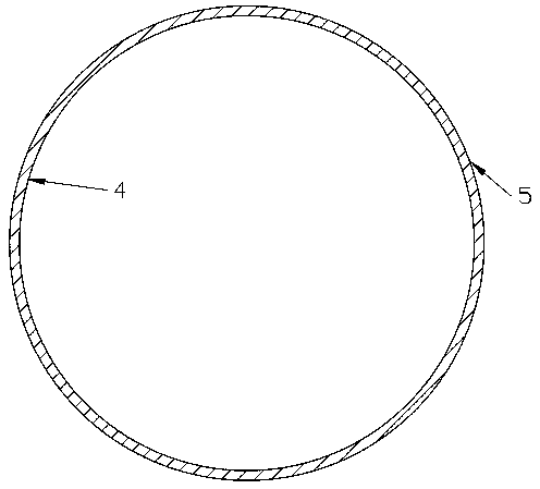
[0065] S2. Carry out scanning path planning for each slice layer, and there are three scanning paths, including a midline 1 and a first conformal line 2 and a second conformal line 3 located on both sides of the midline 1, The midline 1 coincides with the centerline of the slice layer, and the first conformal line 2 is on the slice layer, away from the midline 1 and close to the first contour line 4 of the conformal line 2 Parallel; the second conformal line 3 is parallel to the second contour line 5 on the slice layer, away from the midline 1 and close to the second conformal line 3, and the scanning path is as follows Figure 4 shown. The wall thickness of the thin-walled part is d=...

Embodiment 2

[0072] The laser scanning path planning method for thin-walled parts in this embodiment is basically the same as that in Embodiment 1, the only difference being:

[0073] There are two scanning paths, including the first conformal line 2 and the second conformal line 3, the first conformal line 2 is on the slice layer, away from the center line of the slice layer and close to the slice layer The first contour line 4 of the first conformal line 2 is parallel; the second conformal line 3 is on the slice layer, away from the center line of the slice layer and close to the second conformal line 3. Contour lines 5 are parallel. The first conformal line 2 and the second conformal line 3 are connected.

[0074] The distance between the first conformal line 2 and the first contour line 4 is 3.2 mm, and the distance between the second conformal line 3 and the second contour line 5 is 3.2 mm. The molten pool width is 8mm, and the laser power is 7500W.

[0075] Observing the metal com...

Embodiment 3

[0077] The laser scanning path planning method for thin-walled parts in this embodiment is basically the same as that in Embodiment 1, the only difference being:

[0078] The distance between the first conformal line 2 and the first contour line 4 is 2 mm, and the distance between the second conformal line 3 and the second contour line 5 is 2 mm. The molten pool width is 7mm, and the laser power is 6500W.

[0079] Observing the metal component of this embodiment, the surface is smooth without cracks, and the thickness of the 3D printed blank is 11 mm.


PUM

PropertyMeasurementUnit
thicknessaaaaaaaaaa
widthaaaaaaaaaa

Abstract

The invention relates to the technical field of additive manufacturing, and particularly discloses a method for planning a laser scanning path of a thin-walled part. The method for planning the laserscanning path of the thin-walled part comprises the following steps that a three-dimensional model of the to-be-formed thin-walled part is established and is divided into a plurality of slice layers;and scanning paths of the slice layers are planned, wherein the number of the scanning paths is more than one, and each scanning path comprises a center line coinciding with the center of the corresponding slice and / or a following line parallel to the contour line of the corresponding slice layer. The invention further provides a 3D printing method adopting the method for planning the laser scanning path of the thin-walled part. By the adoption of technical solution, the thickness of a blank of the thin-walled part can be decreased, and the forming quality of the part is improved.

Description

technical field [0001] The invention relates to the technical field of additive manufacturing, in particular to a laser scanning path planning method and a 3D printing method for thin-walled parts. Background technique [0002] Thin-walled parts are increasingly widely used in various industrial sectors because of their light weight, material saving, and compact structure. However, the processing of thin-walled parts is a difficult problem in turning because of poor rigidity and weak strength of thin-walled parts. , It is very easy to deform during processing, which increases the shape and position error of the part, and it is difficult to guarantee the processing quality of the part. Therefore, 3D printing to manufacture thin-walled parts is constantly being promoted. For thin-walled parts, especially large thin-walled parts, when 3D printing is used to manufacture part blanks, due to the small thickness of the parts themselves, it is easy to cause problems such as excessi...

Claims


Application Information

Patent Timeline
Patent Type & Authority Applications(China)
IPC IPC(8): B22F3/105B33Y10/00B33Y50/02
CPCB33Y10/00B33Y50/02B22F10/00B22F10/25B22F10/36B22F10/366Y02P10/25
Inventor 董建新李广生刘斌李欣红
Owner TSC LASER TECH DEV BEIJING CO LTD
Why Eureka
Try Eureka