
Lathes suitable for machining internal threads

A technology of internal thread and lathe, applied in the direction of metal processing equipment, metal processing machinery parts, turning equipment, etc., can solve the problems of large size, high transportation cost, increased processing cost of enterprises, etc., to achieve reduced processing cost, convenient operation, and structural simple effect

Active Publication Date: 2020-07-28
HEBEI HUAFENG ENERGY TECH DEV CO LTD
View PDF5 Cites 0 Cited by
  • Summary
  • Abstract
  • Description
  • Claims
  • Application Information

AI Technical Summary

Problems solved by technology

[0003] However, in the process of production and R&D, if an enterprise needs to process the inner wall of a pipe with a longer length (such as a length of more than ten meters or more than twenty meters) and a larger diameter according to the needs of use, it is used to The internal thread is processed and formed on the inner wall of the pipe, because the chuck equipped by the enterprise itself cannot clamp and fix the pipe with a large diameter, so it cannot realize the rotational drive of the pipe, so that the lathe equipped by the enterprise itself cannot meet such occasional Due to the unique processing requirements, the enterprise needs to entrust the pipes to be processed to a manufacturer dedicated to processing pipes. Since the overall size of the pipes to be processed is large, the corresponding transportation costs are high, and it is necessary to find other manufacturers for processing. Expenses, thus increasing the corresponding processing costs of enterprises

Method used


Image

  • Lathes suitable for machining internal threads
  • Lathes suitable for machining internal threads
  • Lathes suitable for machining internal threads

Examples


Embodiment Construction

[0022] The following will clearly and completely describe the technical solutions in the embodiments of the present invention with reference to the accompanying drawings in the embodiments of the present invention. Obviously, the described embodiments are only some, not all, embodiments of the present invention. Based on the embodiments of the present invention, all other embodiments obtained by persons of ordinary skill in the art without making creative efforts belong to the protection scope of the present invention.

[0023] Unless otherwise defined, all technical and scientific terms used herein have the same meaning as commonly understood by one of ordinary skill in the technical field of the invention. The terms used herein in the description of the present invention are for the purpose of describing specific embodiments only, and are not intended to limit the present invention.

[0024] The lathe suitable for processing internal threads claimed in the present invention ...


PUM


Abstract

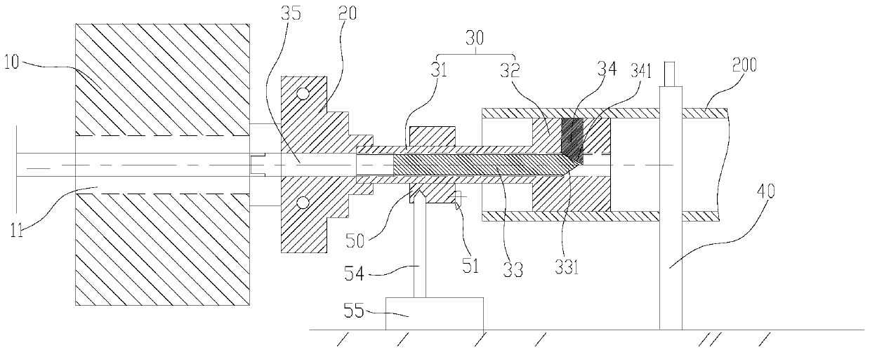
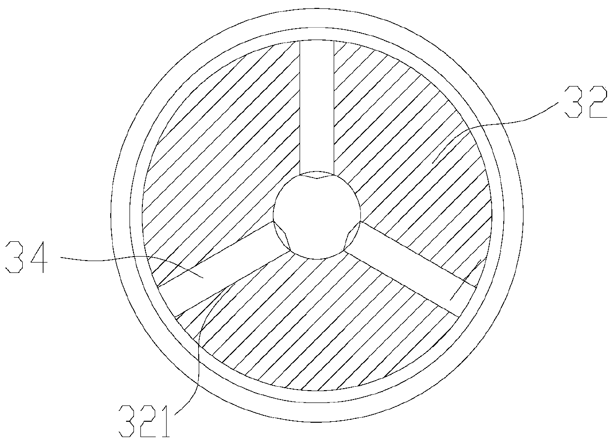
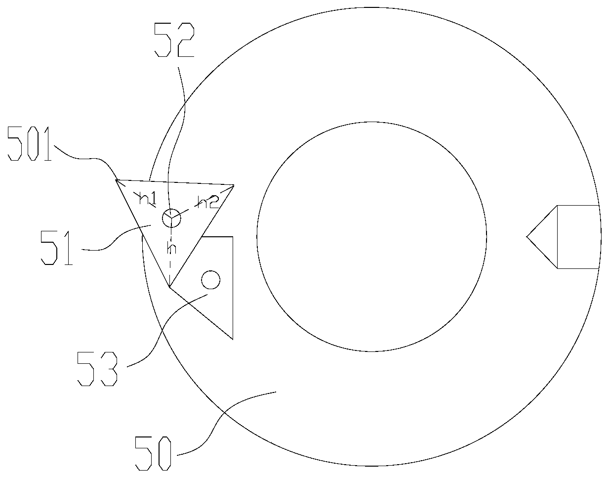
The invention discloses a lathe suitable for machining an internal thread. The lathe comprises a spindle box, a chuck arranged on the spindle box, a fastener used for connecting the chuck with a pipeline, and a center frame used for supporting the pipeline, wherein the fastener comprises a straight pipe part clamped by the chuck, and a disc head part which is perpendicularly arranged at one end ofthe straight pipe part and extends into the pipeline; an ejector rod is in screw joint with the interior of the straight pipe part; a plurality of positioning pins are movably inserted in the disc head part; the ejector rod can push the multiple positioning pins to synchronously extend out of the disc head part, and the multiple positioning pins extending out of the disc head part are matched toclamp the pipeline; the straight pipe part of the fastener is movably sleeved with a tool rest barrel; a turning tool is arranged on the tool rest barrel; and the tool rest barrel can drive the turning tool to move in the axial direction of the straight pipe part on the fastener so as to turn the inner wall of the pipeline. The lathe meets the machining requirement for the internal thread on the inner wall of the pipeline, accordingly, the types and specifications of the pipeline which can be suitable for being turned by the lathe are expanded, and the effect of reducing the machining cost ofenterprises is achieved.

Description

technical field [0001] The invention belongs to the technical field related to lathes, in particular to a lathe suitable for processing internal threads. Background technique [0002] A lathe is a machine tool that mainly uses a turning tool to turn a rotating workpiece. Among them, due to the production cost involved, the company usually equips a lathe with more frequent use in the R&D workshop, which is suitable for the turning processing required by the company's usual production and processing. [0003] However, in the process of production and R&D, if an enterprise needs to process the inner wall of a pipe with a longer length (such as a length of more than ten meters or more than twenty meters) and a larger diameter according to the needs of use, it is used to The internal thread is processed and formed on the inner wall of the pipe, because the chuck equipped by the enterprise itself cannot clamp and fix the pipe with a large diameter, so it cannot realize the rotati...

Claims


Application Information

Patent Timeline
Patent Type & Authority Patents(China)
IPC IPC(8): B23G1/22B23G1/44B23Q3/14B23B5/08
CPCB23B5/08B23G1/225B23G1/44B23Q3/14
Inventor 许晓波王庆国
Owner HEBEI HUAFENG ENERGY TECH DEV CO LTD
Learn More