Lifting mechanism of double-wheel trench cutting and stirring machine and double-wheel trench cutting and stirring machine

A mixer and double-wheel milling technology, applied in drilling equipment, earth-moving drilling, drill pipe and other directions, can solve the problems of shortening the life of drill pipe and hoisting mechanism, complex pulley block, large friction resistance, etc. Good quality of walls and the effect of preventing contact

Pending Publication Date: 2020-02-04
XUZHOU XUGONG FOUND CONSTR MACHINERY
View PDF0 Cites 0 Cited by
  • Summary
  • Abstract
  • Description
  • Claims
  • Application Information

AI Technical Summary

Problems solved by technology

However, the pulley block in the hoisting mechanism is more complicated, the steel wire rope used is longer, the friction resistance is large, and the efficiency is low.
[0006] 3. The guide wheels of the lifting mechanism are arranged on one side in the up and down direction, and the guiding performance is poor. This will cause the lifting mechanism to grind with the drill pipe during the lifting and lowering process, reducing the life of the drill pipe and the lifting mechanism

Method used


Image

  • Lifting mechanism of double-wheel trench cutting and stirring machine and double-wheel trench cutting and stirring machine
  • Lifting mechanism of double-wheel trench cutting and stirring machine and double-wheel trench cutting and stirring machine
  • Lifting mechanism of double-wheel trench cutting and stirring machine and double-wheel trench cutting and stirring machine

Examples


Embodiment Construction

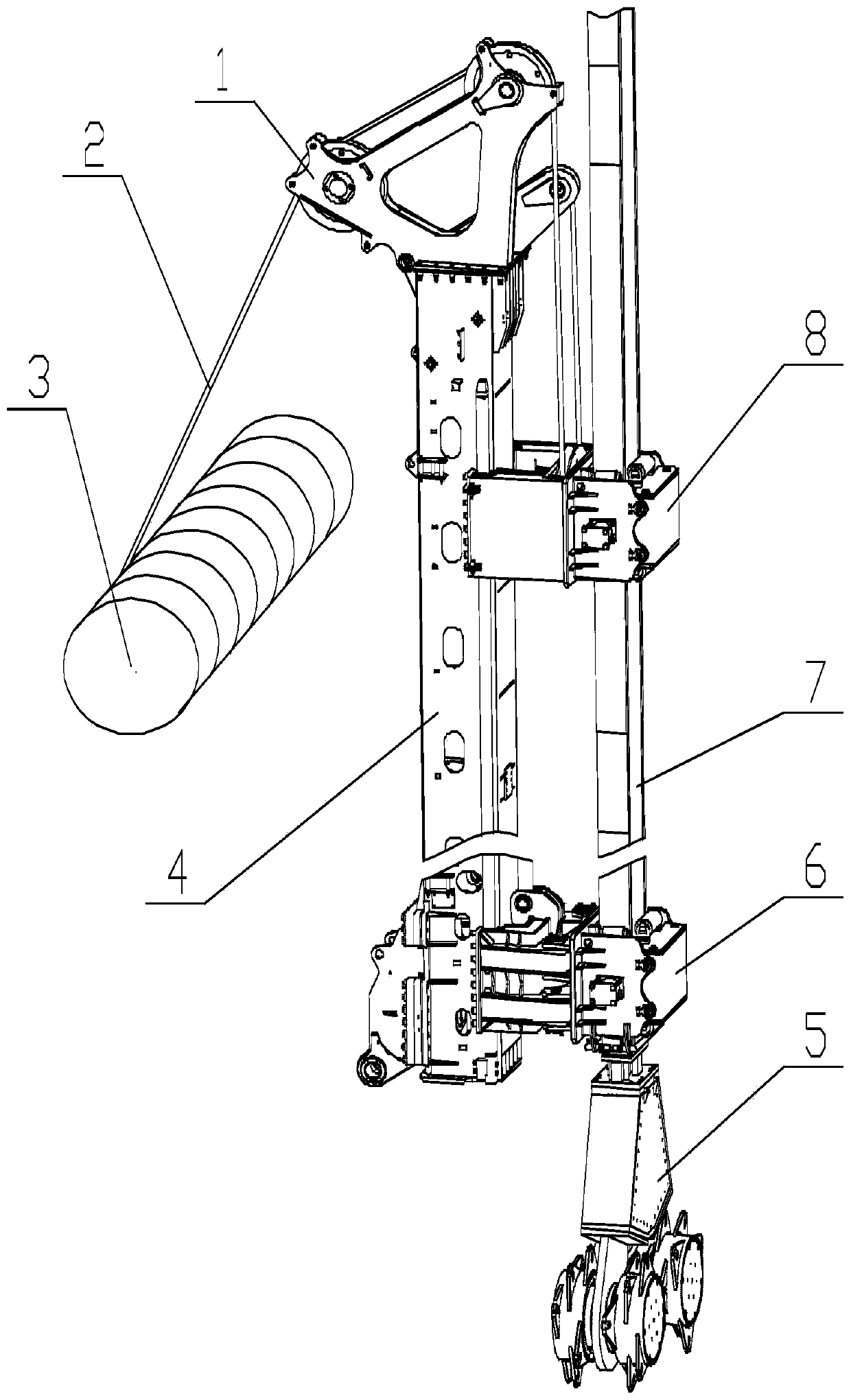
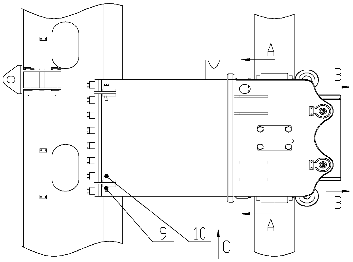
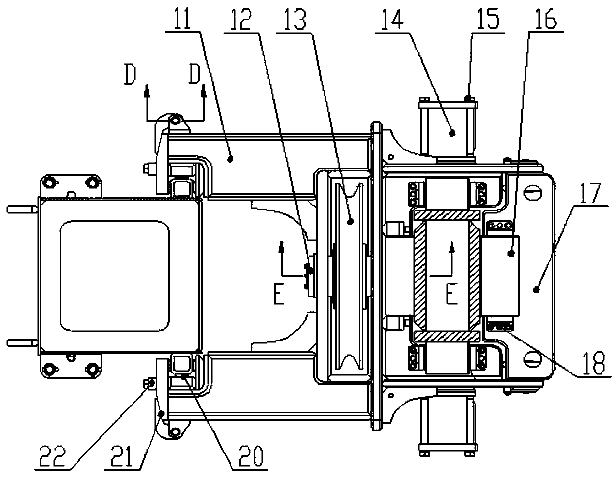
[0041]In order to make the objectives, technical solutions and advantages of the present invention clearer, the technical solutions in the embodiments of the present invention will be described in more detail below in conjunction with the drawings in the embodiments of the present invention. In the drawings, the same or similar reference numerals denote the same or similar elements or elements having the same or similar functions throughout. The described embodiments are some, but not all, embodiments of the invention. The embodiments described below by referring to the figures are exemplary and are intended to explain the present invention and should not be construed as limiting the present invention. Based on the embodiments of the present invention, all other embodiments obtained by persons of ordinary skill in the art without making creative efforts belong to the protection scope of the present invention. Embodiments of the present invention will be described in detail be...


PUM


Abstract

The invention discloses a lifting mechanism of a double-wheel trench cutting and stirring machine and the double-wheel trench cutting and stirring machine. The lifting mechanism comprises a lifting frame, a movable pulley, a guide component, pressing plate components and a front face plate, wherein each of the two sides of the rear end of the lifting frame is provided with one of the symmetrical pressing plate components, and the pressing plate components and the lifting frame form a groove-shaped slideway; a sliding block is arranged in the groove-shaped slideway and is used for realizing sliding on a mast of a drilling machine; the movable pulley is arranged at the middle part of the lifting frame through a pin I; a steel wire rope on a main winch sequentially passes through a pulley group of a goose head pulley carrier fixed at the top end of the mast of the drilling machine and the movable pulley on the lifting frame and is finally fixed on the goose head pulley carrier; the frontface plate is fixed on the lifting frame through a pin II; and the guide component is arranged between the lifting frame and the front face plate so as to prevent connect between a drill rod and the lifting frame. The lifting mechanism and the double-wheel trench cutting and stirring machine ensure that after the process of clamping the drill rod, the drill rod is in the middle position, and shaking is effectively reduced; and the movable pulley is arranged on the lifting frame, so that the lifting capacity of the lifting mechanism is improved.

Description

technical field [0001] The invention relates to a double-wheel milling mixer, in particular to a double-wheel milling mixer lifting mechanism, which belongs to the technical field of the double-wheel milling mixer lifting mechanism. Background technique [0002] The double-wheel milling mixer is a kind of equipment used for mixing and forming walls in complex strata. Specifically, it is a kind of diaphragm wall construction that can realize complex strata such as hard strata, rocks and pebbles. At the same time, it can stir the cement slurry while lifting the drill pipe. Wall-forming equipment is mainly used for drilling in hard ground and grouting and mixing to form walls. [0003] At present, the structure of various double-wheel milling mixers at home and abroad is roughly the same. During use, there are the following defects: [0004] 1. The lifting mechanism of the double-wheel milling and mixing drilling rig adopts a single oil cylinder structure for clamping the dri...

Claims


Application Information

Patent Timeline
Patent Type & Authority Applications(China)
IPC IPC(8): E21B19/14E21B19/084E21B19/10E21B19/24
CPCE21B19/084E21B19/10E21B19/14E21B19/24
Inventor 罗菊孙余苏伟崔刚王选卓丁佐川刘威阙佳豪
Owner XUZHOU XUGONG FOUND CONSTR MACHINERY
Why Eureka
Try Eureka