Liquid cooling charging system for new energy automobile and control method

A new energy vehicle and charging system technology, applied in electric vehicle charging technology, charging stations, electric vehicles, etc., can solve the problems of terminals and wiring harnesses with poor heat dissipation and heat dissipation

Active Publication Date: 2020-02-07
ZHONGTONG BUS HLDG
View PDF11 Cites 2 Cited by
  • Summary
  • Abstract
  • Description
  • Claims
  • Application Information

AI Technical Summary

Problems solved by technology

[0005] The present invention aims at the above-mentioned technical problems existing in the charging of electric vehicles, and proposes a design with reasonable design, simple structure, low cost, and can solve the problem of serious heating of the terminals and wire harnesses and poor heat dissipation effect when the charging socket is charged with high current, and at the same time Monitoring charging safety during charging A liquid-cooled charging system and control method for new energy vehicles

Method used


Image

  • Liquid cooling charging system for new energy automobile and control method
  • Liquid cooling charging system for new energy automobile and control method
  • Liquid cooling charging system for new energy automobile and control method

Examples


Embodiment 1

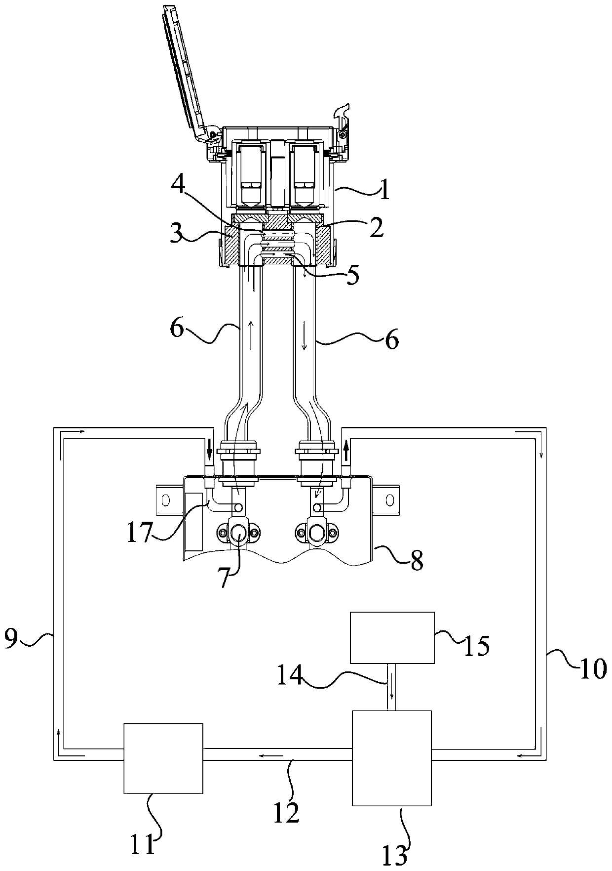
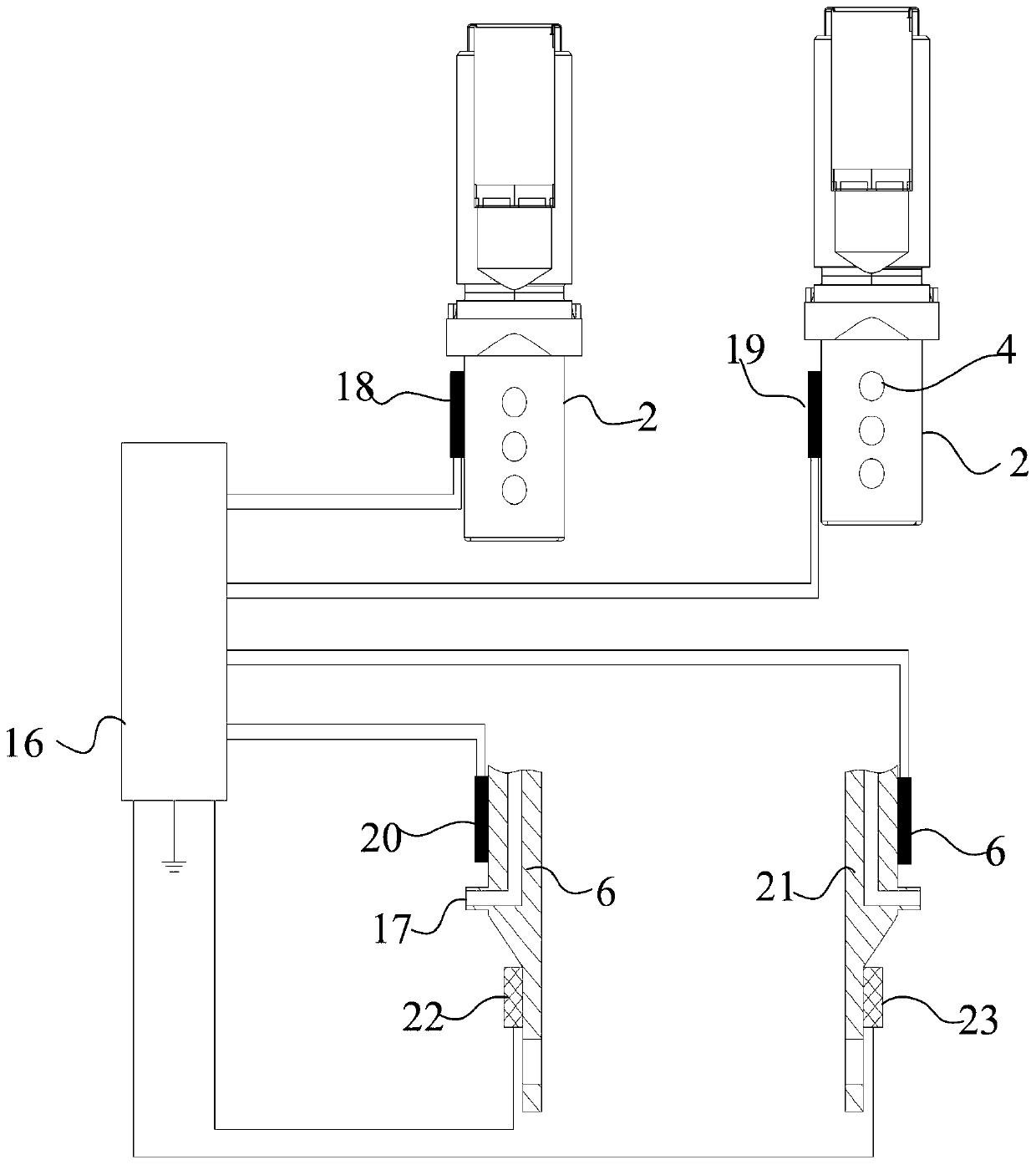
[0037] Example 1, such as figure 1 , figure 2 As shown, this embodiment provides a liquid-cooled charging system for new energy vehicles. Like the existing liquid-cooled charging system for new energy vehicles, the liquid-cooled charging system for new energy vehicles provided by this embodiment includes a charging socket, a water pump , water inlet pipe, water outlet pipe, connecting water pipe, cooling water tank, power distribution unit, and safety monitoring box. A water outlet pipe is provided at one end, and two liquid-cooled wires arranged side by side are arranged at the bottom of the charging socket. The bottom is provided with a sealed nest for fixing the charging liquid-cooled terminal. The liquid-cooled wires are connected to each other, and the liquid-cooled wires are respectively connected to the water inlet pipe and the water outlet pipe. The above structure is an existing common structure, so in this embodiment, no Add a detailed description.

[0038] The k...

Embodiment 2

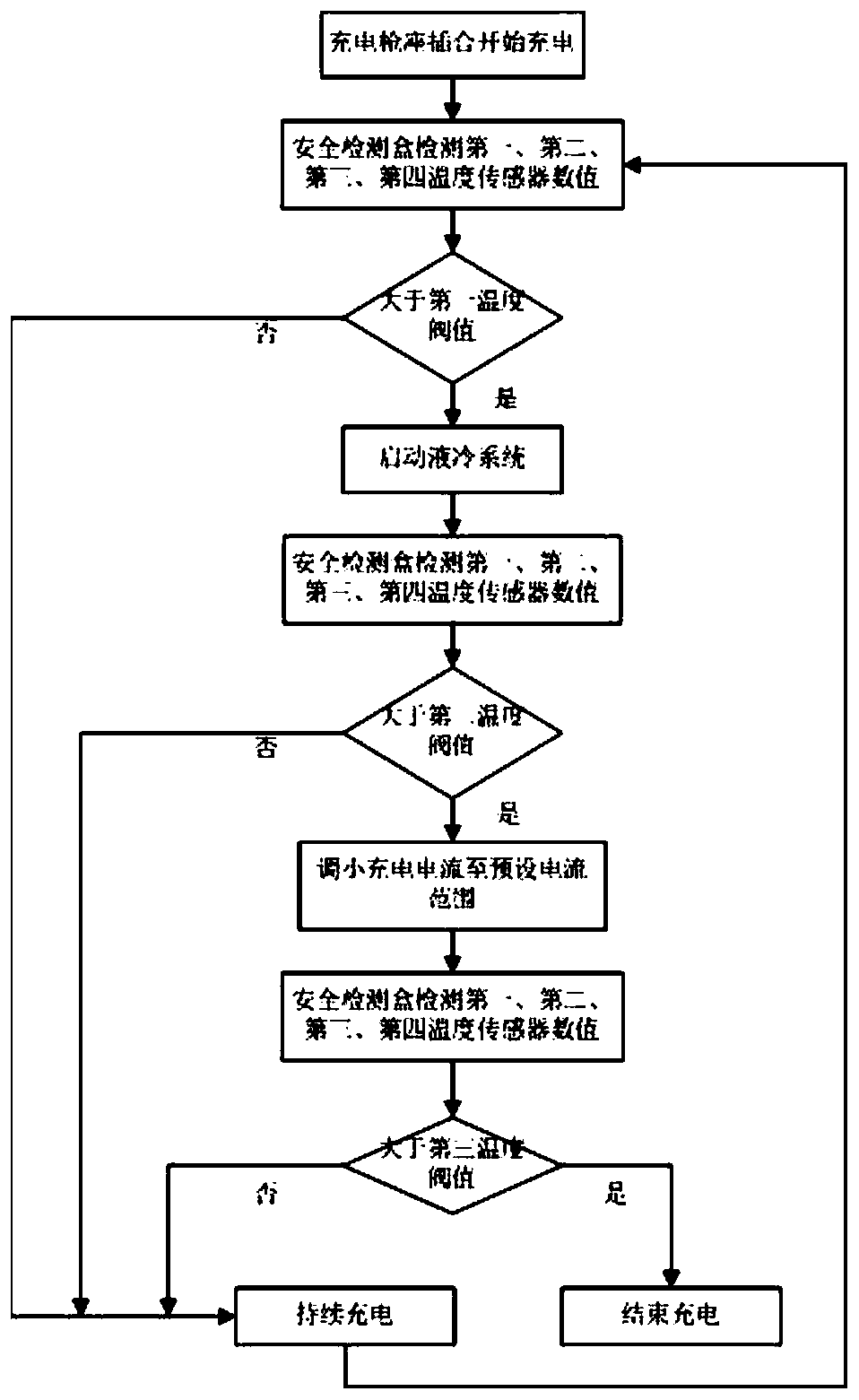
[0045] Embodiment 2. In order to realize accurate and safe control of the liquid-cooled charging system for new energy vehicles provided in Embodiment 1, this embodiment provides a control method for the above-mentioned liquid-cooled charging system for new energy vehicles

[0046] First, set the first temperature threshold, the second temperature threshold and the third temperature threshold, wherein the first temperature threshold is the critical value for the water pump to start working, the second temperature threshold is the critical value for the charging socket operating temperature, and the third temperature threshold is It is the critical value of the operating temperature of the charging socket under the condition of low current.

[0047] Then, acquire the temperature values ​​of the first temperature sensor, the second temperature sensor, the third temperature sensor and the fourth temperature sensor;


PUM


Abstract

The invention belongs to the technical field of charging of new energy vehicles, and particularly relates to a liquid cooling charging system for a new energy vehicle and a control method. The systeminvolves a charging socket, a water pump, a water inlet pipe, a water outlet pipe, a connecting water pipe, a heat dissipation water tank, a power distribution unit and a safety monitoring box, wherein the water pump and the heat dissipation water tank are connected through the connecting water pipe, the water inlet pipe is arranged at the end, away from the connecting water pipe, of the water pump, and the water outlet pipe is arranged at the end, away from the connecting water pipe, of the heat dissipation water tank. According to the liquid cooling charging system for the new energy vehicleand the control method, through the reasonable structural arrangement, the cooling effect of the liquid cooling charging system is effectively improved; through temperature sensors arranged on a charging liquid cooling terminal and a liquid cooling terminal, temperature monitoring is carried out, and the safety of the charging process is guaranteed; and meanwhile, through the arrangement of a cooling liquid insulation detection module, the insulation failure problem due to the long-term use of cooling liquid is avoided.

Description

technical field [0001] The invention belongs to the technical field of new energy vehicle charging, and in particular relates to a liquid-cooled charging system and a control method for new energy vehicles. Background technique [0002] With the rapid development of global industry, the ecological environment is being destroyed day by day, and environmental protection issues are gradually put on the agenda. Exhaust emissions from automobiles account for most of the environmental pollution. If we want to promote environmental protection, we must solve the problem of exhaust emissions from traditional automobiles. For this reason, due to the use of advanced technology, new energy vehicles have effectively achieved low-carbon and environmentally friendly travel, and have been widely promoted. [0003] In recent years, in the process of practical application and promotion of new energy vehicles, the two main factors affecting the development of electric vehicles are driving ran...

Claims


Application Information

Patent Timeline
Patent Type & Authority Applications(China)
IPC IPC(8): B60L53/16B60L53/302H01R13/02H01R13/66
CPCB60L53/16B60L53/302H01R13/02H01R13/6683H01R2201/26Y02T10/70Y02T10/7072Y02T90/12Y02T90/14
Inventor 囤金军徐彪范志先刘涛魏琳于如兴
Owner ZHONGTONG BUS HLDG
Why Eureka
Try Eureka