Powder tank and material level control method thereof

A technology of powder tanks and powder materials, which is applied in the field of powder tanks of mixing stations, can solve the problems of inability to accurately control the amount of powder materials, and achieve the effects of avoiding insufficient materials, prolonging service life, and avoiding production stoppage due to lack of materials

Pending Publication Date: 2020-02-07
MAANSHAN HONGTAI BUILDING MATERIALS
View PDF1 Cites 0 Cited by
  • Summary
  • Abstract
  • Description
  • Claims
  • Application Information

AI Technical Summary

Problems solved by technology

[0006] Aiming at the problem that the amount of powder in the powder tank of the mixing station cannot be precisely controlled in the prior art, the present invention provides a powder tank and its material level control method, which uses the floating ball material that can be floated by blown by the air flow of the injection material. The positioner can give real-time feedback on the remaining amount of powder in the powder tank, so as to help the staff determine when to replenish the powder and the amount of powder to be replenished, so as to avoid warehouse explosion or stop production due to lack of material due to insufficient remaining material. The airflow pushes the floating ball level sensor that can float for material level collection and feedback. The structure is simple, and there is no need to improve the structure of the powder tank body, and the cost is low; compared with manual warehouse inspection, it is safer

Method used


Image

  • Powder tank and material level control method thereof
  • Powder tank and material level control method thereof
  • Powder tank and material level control method thereof

Examples


Embodiment 1

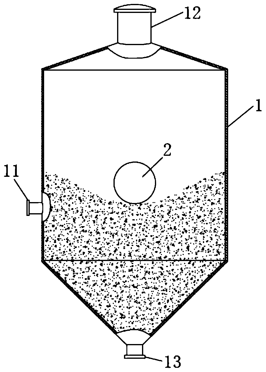
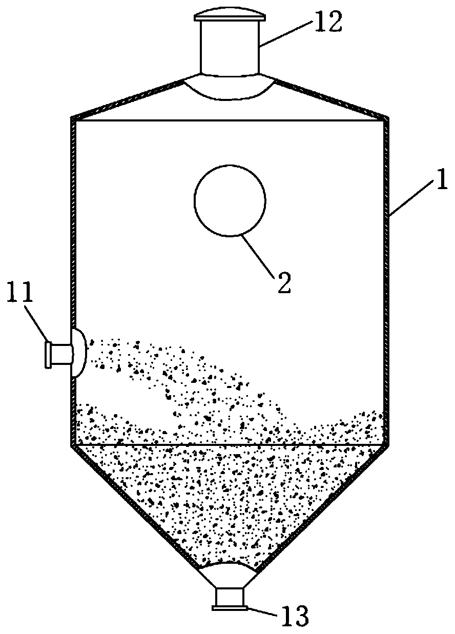
[0039] Such as figure 1 with figure 2 As shown in , a powder tank in this embodiment includes a powder tank body 1, a feed port 11 is provided at the waist, a discharge port 13 is provided at the bottom, and a dust collector 12 is provided at the top; it also includes a floating ball The material level device 2 floats on the surface of the powder in the powder tank body 1 to collect and feed back the material level of the powder in the powder tank body 1 in real time. The ratio of the gravity of the float level device 2 to the buoyancy of the air is 1:0.7-0.9, which ensures that it can float when it is impacted by the injection air flow, so as to avoid being submerged by the injected powder; Finally, because its own gravity is greater than the received buoyancy, it can ensure that it slowly falls to the surface of the powder, thereby collecting the material level height of the powder in the powder tank body 1. In this embodiment, the ratio of the gravity of the float level ...

Embodiment 2

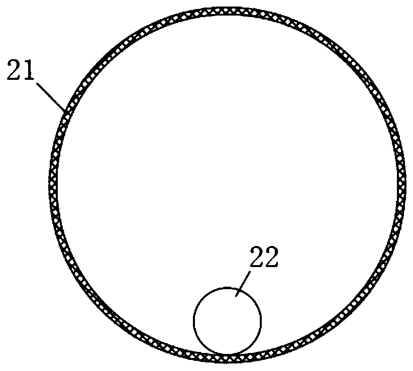
[0048] The powder tank in the present embodiment is basically the same as in Embodiment 1, the differences and improvements are as follows: Figure 4 As shown in , the side wall of the sphere 21 includes an airtight layer 211 , a puncture-resistant layer 212 and a wear-resistant layer 213 from inside to outside. The airtight layer 211 is arranged on the innermost layer of the sphere 21 to form a seal inside the sphere 21 to prevent the light gas inside the sphere 21 from leaking, and the innermost layer will not touch hard object, and then will not be worn and punctured, and the sealing performance is always better after long-term use; The airtight layer 211 is used to prevent the sphere 21 from being pierced after hitting a hard object; the wear-resistant layer 213 is arranged outside the puncture-resistant layer 212 to increase the wear resistance of the surface of the sphere 21 , to prevent the ball 21 from being worn out after long-term use.

[0049] Such as Figure 4 A...

Embodiment 3

[0053] The powder tank in the present embodiment, basic structure is the same as embodiment 2, difference and improvement are, as Figure 4 As shown in , the sphere 21 is provided with a gas injection nozzle 23 for filling the sphere 21 with light gas.

[0054] After long-term use, the light gas in the sphere 21 will permeate out of the sphere 21, causing the float level device 2 to fail because it is not easy to float, so it is necessary to replace the float level device 2 regularly, resulting in Waste of cost.

[0055] In this embodiment, by setting the gas injection nozzle 23 on the sphere 21, when the float level gauge 2 fails to float, take out the float level gauge 2 from the powder tank body 1 , and then supplement the light gas into the sphere 21 through the gas injection nozzle 23, so that the float level device 2 can be used repeatedly and the replacement cost can be reduced.


PUM


Abstract

The invention discloses a powder tank and a material level control method thereof, and belongs to the technical field of stirring station powder tanks. The powder tank comprises a powder tank body, the waist of the powder tank body is provided with a feeding port, the bottom of the powder tank body is provided with a discharging port, and the top of the powder tank body is provided with a dust remover; the powder tank further comprises a floating ball level device which floats on the surface of the powder in the powder tank body so as to collect and feedback the level height of the powder in the powder tank body in real time; the floating ball level device comprises a ball body and a sensor arranged in the ball body, and a light gas is filled in the ball body to provide buoyancy for the ball body. According to the low-material position point in the powder tank body collected in real time by the floating ball level device, a worker is helped to determine when to supplement materials anddetermine the amount of the fed powder, so that the bin full or the material shortage stopping production is avoided; and the floating ball level device capable of being floated by airflow is adoptedfor carrying out material level acquisition and feedback, the structure is simple, the structure of the powder tank body does not need to be improved, and the cost is low; and manual bin checking isnot needed, and the safety is high.

Description

technical field [0001] The invention relates to the technical field of a mixing station powder tank, in particular to a powder tank and a material level control method thereof. Background technique [0002] The powder tank is an important part of the mixing plant. It is used to store powder such as cement, admixtures, and dry powder additives. Since the powder tank is filled with powder, it needs to be sealed to prevent the powder from leaking out and causing environmental damage. Pollution and personal injury. The powder tank is bulky, and the powder needs to be transported into the tank by an air pump. In the prior art, when the tank is sealed, how much powder is there in the powder tank? How much powder still needs to be injected? It is entirely dependent on the estimation of the staff, so it is impossible to accurately locate the depth of the material level in the powder tank, which makes it difficult to determine the amount of powder to be added to the powder tank. ...

Claims


Application Information

Patent Timeline
Patent Type & Authority Applications(China)
IPC IPC(8): B65D88/54B65D90/00B65D90/48
CPCB65D88/54B65D90/00B65D90/48
Inventor 梁梦琦梁俊曾少雷
Owner MAANSHAN HONGTAI BUILDING MATERIALS
Why Eureka
Try Eureka