Enameled wire paying-off machine

A technology of enameled wire and pay-off machine, which is applied in the field of enameled wire, can solve the problems such as the incision is not smooth enough, affecting the processing operation, and the conveying interruption, and achieves the effect of solving the single pay-off speed and improving the practicability.

Inactive Publication Date: 2020-02-07
HUNAN SHENGSHI WIRE & CABLE CO LTD
View PDF10 Cites 0 Cited by
  • Summary
  • Abstract
  • Description
  • Claims
  • Application Information

AI Technical Summary

Problems solved by technology

[0003] Before the enameled wire is officially put into use, most of it needs to be processed to meet the standard requirements for normal use. The existing enameled wire processing equipment is generally used in conjunction with the pay-off machine. Although the existing pay-off machine can It meets the basic needs of pay-off, but its disadvantages are also very obvious, mainly as follows: the tension and friction force during the pay-off process of different specifications of enameled wire are different, but the structure of the pay-off device is mostly fixed, which leads to enameled wire It is prone to breakage, which affects the processing operation; before the enameled wire is unwound, most of the enameled wires are wrapped together in a ring, and the enameled wire pulled out is in a state of bending and undulation, which may be in the subsequent transmission. There is a problem of interruption of conveying, and the cut will not be smooth enough when cutting; some pay-off machines lack speed regulating mechanisms, and the pay-off speed cannot be adjusted according to different processing equipment

Method used


Image

  • Enameled wire paying-off machine
  • Enameled wire paying-off machine
  • Enameled wire paying-off machine

Examples


Embodiment Construction

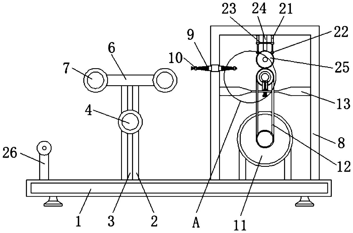
[0023] The following will clearly and completely describe the technical solutions in the embodiments of the present invention with reference to the accompanying drawings in the embodiments of the present invention. Obviously, the described embodiments are only some, not all, embodiments of the present invention. Based on the embodiments of the present invention, all other embodiments obtained by persons of ordinary skill in the art without making creative efforts belong to the protection scope of the present invention.

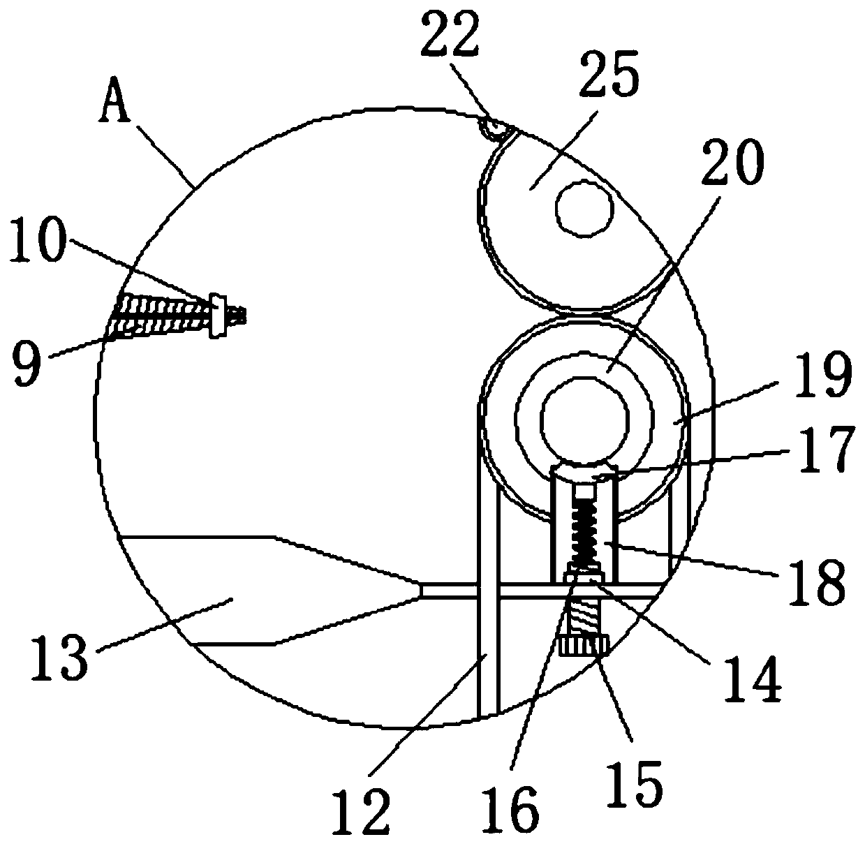
[0024] see Figure 1-4 , an enameled wire pay-off machine, including a chassis 1, the left side of the top surface of the chassis 1 is fixedly connected with a pillar 2 perpendicular to the chassis 1, the middle part of the pillar 2 is provided with a chute 3, and the chute is opened in the middle part of the pillar 2 3 design, so that the first round roller 4 can slide up and down along the chute 3, when the pulling force of the device on the enameled wire is...


PUM


Abstract

The invention relates to the technical field of enameled wires, and discloses an enameled wire paying-off machine. The machine comprises a chassis. The left side of the top face of the chassis is fixedly connected with a supporting column perpendicular to the chassis, a sliding groove is formed in the middle of the supporting column, a first circular roller is clamped to the middle of the front face of the sliding groove, one side of the back face of the first circular roller is fixedly connected to one side of a first spring, the other end of the first spring is fixedly connected to the top face of the chassis, the top end of the first circular roller is fixedly connected to the middle of the bottom face of the connecting rod, and second circular rollers are clamped to the left and rightends of the connecting rod respectively. By adopting the design of the vertically-movable first circular roller, on the basis of the joint use of the second circular rollers at the two sides of the top, when the device is in use, excessively-large paying-off acting force can be transferred to the first circular roller, the buffering effect is achieved, the problem that enameled wires are pulled apart by excessively-large paying-off acting force is avoided is avoided, and the practicability of the paying-off machine is achieved.

Description

technical field [0001] The invention relates to the technical field of enameled wires, in particular to an enameled wire pay-off machine. Background technique [0002] Enameled wire refers to the metal wire used to wind the electromagnetic coil with insulating varnish as the insulating coating. It is also called electromagnetic wire. It is a main variety of winding wire. , and then painted and baked many times, with the rapid development of industrial appliances, household appliances, telecommunications, electronic products, etc., the enameled wire has brought a wider application field and market. my country has become the world's enameled wire manufacturing center and processing base, and is the world's largest enameled wire production and sales country, accounting for about 30% of the world's total output. The production volume of China's enameled wire has been increasing at an annual rate of more than 10% in the past two decades. [0003] Before the enameled wire is off...

Claims


Application Information

Patent Timeline
Patent Type & Authority Applications(China)
IPC IPC(8): B65H49/20B65H51/08
CPCB65H49/20B65H51/08B65H2701/34
Inventor 赵德良赵旭曹知平
Owner HUNAN SHENGSHI WIRE & CABLE CO LTD
Why Eureka
Try Eureka