Supercharge Your Innovation With Domain-Expert AI Agents!

Self-floating low-flow-rate river power generation device capable of lifting along with water level

A power generation device, self-floating technology, applied in hydropower, reaction engines, floating buildings, etc., can solve the problems of large pollutant discharge, long cable deployment length, large vertical water level drop, etc., and achieve high power generation Efficiency, Ensuring Work Efficiency, Ensuring Sustainability

Pending Publication Date: 2020-02-07
CHONGQING JIAOTONG UNIVERSITY
View PDF9 Cites 0 Cited by
  • Summary
  • Abstract
  • Description
  • Claims
  • Application Information

AI Technical Summary

Problems solved by technology

At present, the energy supply of the port is mainly based on diesel oil, traditional thermal power, and natural gas, but the amount of pollutants is large, and the connection of cables such as shore bridges and shore power has a great impact on the environment of the port area, especially in the Three Gorges Dam area, where port terminals on mountainous rivers are used as inland rivers It is an important part of the wharf. During the operation of the wharf, it faces complex hydrological conditions such as large flow velocity (water velocity > 3.0m / s), large water depth (water depth > 20m) and large water level difference (water level difference > 30m). The vertical water level drop is large, The length of the cable is long, the operation is difficult, and there is a certain safety risk, which seriously affects the promotion and application of port shore power.

Method used


Image

  • Self-floating low-flow-rate river power generation device capable of lifting along with water level
  • Self-floating low-flow-rate river power generation device capable of lifting along with water level
  • Self-floating low-flow-rate river power generation device capable of lifting along with water level

Examples


Embodiment 1

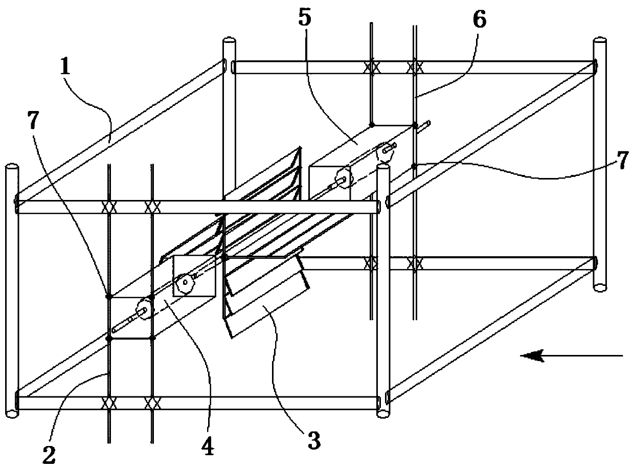
[0031] This embodiment discloses a self-floating low-velocity river power generation device that can rise and fall with the water level, including a rotating assembly 3, a power generation assembly 4, and a buoy 5 arranged under the overhead vertical wharf, and the materials used to make the rotating assembly 3 and the buoy 5 The density is less than that of water.

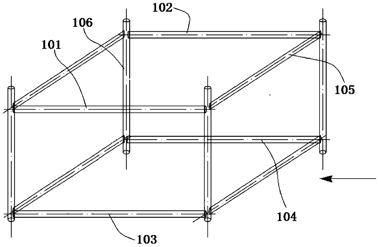
[0032] Several square support frames 1 are connected to the lower end of the overhead vertical wharf. see figure 2 , the square supporting frame 1 includes beam I101, beam II102, beam III103, beam IV104, four longitudinal beams 105 and four columns 106, beam I101, beam II102 and two longitudinal beams 105 spliced ​​into an upper rectangular frame, beam III103 , beam IV 104 and two longitudinal beams 105 are spliced ​​into a lower rectangular frame, and four columns 106 connect the upper rectangular frame and the lower rectangular frame as a whole.

[0033] The beam I 101 , beam II 102 , beam III 103 and beam IV...

Embodiment 2

[0047] This embodiment discloses a self-floating low-velocity river power generation device that can rise and fall with the water level, including a rotating assembly 3, a power generation assembly 4, and a buoy 5 arranged under the overhead vertical wharf, and the materials used to make the rotating assembly 3 and the buoy 5 The density is less than that of water.

[0048] Several square support frames 1 are connected to the lower end of the overhead vertical wharf. see figure 2 , the square supporting frame 1 includes beam I101, beam II102, beam III103, beam IV104, four longitudinal beams 105 and four columns 106, beam I101, beam II102 and two longitudinal beams 105 spliced ​​into an upper rectangular frame, beam III103 , beam IV 104 and two longitudinal beams 105 are spliced ​​into a lower rectangular frame, and four columns 106 connect the upper rectangular frame and the lower rectangular frame as a whole.

[0049] The beam I 101 , beam II 102 , beam III 103 and beam IV...

Embodiment 3

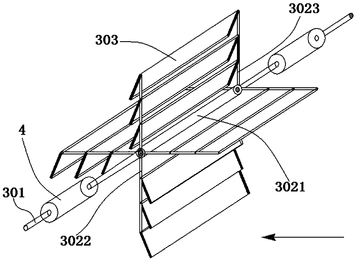
[0060] The main structure of this embodiment is the same as that of Embodiment 3, further, see Figure 5 In Figure (2), when the steel pipe I, steel pipe II, steel pipe III, steel pipe IV, steel pipe V, steel pipe VI, steel pipe VII and steel pipe VIII are all curved steel pipes, the plate surface of the blade 303 is a curved surface. When working, the concave side of steel pipe I, steel pipe II, steel pipe III, steel pipe IV, steel pipe V, steel pipe VI, steel pipe VII and steel pipe VIII is the side facing the water, and when several blades 303 are closed, the curved steel pipe The curved surface is marked as curved surface L1, and several blades 303 hinged on the arc-shaped steel pipe are all on the curved surface L1.


PUM


Abstract

The invention discloses a self-floating low-flow-rate river power generation device capable of lifting along with water level, relates to the technical field of water conservancy power generation machinery, and aims to provide a power generation device capable of utilizing a complex water flow environment and providing shore power for a port. The self-floating low-flow-rate river power generationdevice capable of lifting along with the water level comprises a rotating assembly and a power generation assembly, wherein the rotating assembly and the power generation assembly are arranged in a longitudinal and transverse beam structure below an overhead vertical wharf. The rotating assembly and the power generation assembly are made of low-density materials and can float on the water surface.The rotating assembly is provided with a plurality of blades, the blades drive the rotating assembly to rotate under the impact of water flow, the power generation assembly converts kinetic energy ofthe rotating assembly into electric energy, and the electric energy of the power generation assembly is transmitted to an energy storage battery through a transmission line for partial shore power use. The device provided by the invention is suitable for amplitude variation of large water level difference to float up and down, utilizes natural conditions to generate power, and achieves the purposes of green, energy saving and environmental protection.

Description

technical field [0001] The invention relates to the technical field of hydraulic power generation machinery, in particular to a self-floating low-velocity river power generation device that can rise and fall with the water level. Background technique [0002] With the implementation of national strategies such as the construction of golden waterways and the development of the Yangtze River Economic Belt, the level of inland waterways has been further improved. At present, large ships of 5,000 tons and above have gradually become the main type of freight ships, and large ships need to consume a lot of energy when they are in the port area. At present, the energy supply of the port is mainly based on diesel oil, traditional thermal power, and natural gas, but the amount of pollutants is large, and the connection of cables such as shore bridges and shore power has a great impact on the environment of the port area, especially in the Three Gorges Dam area, where port terminals on...

Claims


Application Information

Patent Timeline
Patent Type & Authority Applications(China)
IPC IPC(8): F03B13/00F03B3/14F03B11/00B63B35/44
CPCB63B35/44B63B2035/4466F03B3/14F03B11/00F03B13/00Y02E10/20
Inventor 阿比尔的朱晨浩刘明维张洁梁越余奎丛宇
Owner CHONGQING JIAOTONG UNIVERSITY
Features
  • R&D
  • Intellectual Property
  • Life Sciences
  • Materials
  • Tech Scout
  • Unparalleled Data Quality
  • Higher Quality Content
  • 60% Fewer Hallucinations
Learn More