Supercharge Your Innovation With Domain-Expert AI Agents!

Fluid conveying device

A technology for fluid transportation and installation, which is applied in the direction of pump devices, noise reduction devices, exhaust devices, etc. It can solve the problems of reducing the working efficiency of urea solution and measuring accuracy, and achieve the goal of eliminating air bubbles, ensuring working efficiency and improving the waterproof level Effect

Pending Publication Date: 2020-03-06
TENNECO SUZHOU EMISSION SYST
View PDF0 Cites 0 Cited by
  • Summary
  • Abstract
  • Description
  • Claims
  • Application Information

AI Technical Summary

Problems solved by technology

[0003] However, in actual use, some air bubbles are often produced in the system pipeline, which will reduce the working efficiency and metering accuracy of the urea pump for pumping urea solution.

Method used


Image

  • Fluid conveying device
  • Fluid conveying device
  • Fluid conveying device

Examples


Embodiment Construction

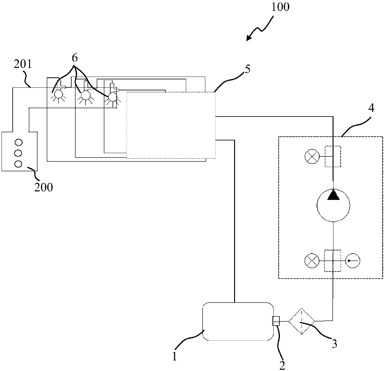
[0022] Please refer to figure 1 As shown, the present invention discloses an engine exhaust gas treatment system 100 , which is applied to the exhaust gas treatment of an engine 200 . The engine exhaust treatment system 100 includes a urea tank 1, a sensor integration device 2 connected to the urea tank 1, a filter 3 connected downstream of the sensor integration device 2, and a fluid delivery device for delivering the urea solution 4. A common rail 5 connected to the fluid delivery device 4 and a nozzle 6 connected to the common rail 5 . In the illustrated embodiment of the present invention, the engine 200 is a high-power engine whose power generally exceeds 500 kilowatts. Correspondingly, the nozzle 6 usually has a plurality. The nozzle 6 is used for spraying urea solution into the engine exhaust pipe 201 . The atomized urea solution is decomposed into ammonia gas in the engine exhaust pipe 201 , and the ammonia gas can react with nitrogen oxides in the exhaust gas, ther...


PUM


Abstract

The invention relates to a fluid conveying device, and is used for conveying urea solution in an engine off-gas treatment system. The fluid conveying device comprises an integrated cabinet, a pump which is installed in the integrated cabinet, an inlet pipeline which is connected with the pump and an outlet pipeline which is connected with the pump, the pump comprises a motor at the bottom part, apump head at the top part and a magnetic coupling part which is located between the motor and the pump head, the pump head, the magnetic coupling part and the motor are arranged from top to bottom, the pump head is internally provided with a U-shaped flow channel and a gear mechanism which is located at the very bottom of the flow channel, and the integrated cabinet comprises a door plate and an annular sealing part which is used for sealing the corresponding part between the door plate and the integrated cabinet. According to the fluid conveying device, the waterproof level is improved.

Description

technical field [0001] The invention relates to a fluid delivery device, in particular to a fluid delivery device arranged in an engine exhaust gas treatment system. Background technique [0002] The engine exhaust gas treatment system in the prior art generally includes a urea tank, a urea pump for pumping urea solution out of the urea tank, and a nozzle connected with the urea pump. The nozzle is used for spraying atomized urea into the exhaust pipe of the engine to realize the purification of exhaust gas. [0003] However, in actual use, some air bubbles are often generated in the system piping, and these air bubbles will reduce the working efficiency and metering accuracy of the urea pump for pumping urea solution. [0004] In addition, if the engine exhaust gas treatment system is applied in harsh environmental conditions, it needs to be further improved. Contents of the invention [0005] The purpose of the present invention is to provide a fluid conveying device w...

Claims


Application Information

Patent Timeline
Patent Type & Authority Applications(China)
IPC IPC(8): F01N3/28F04D13/06F16F15/04
CPCF01N3/28F01N2610/02F01N2610/14F04D13/024F04D13/06F16F15/04F16F2230/0029F16F2238/026
Inventor 陈川孙树平林银山
Owner TENNECO SUZHOU EMISSION SYST
Features
  • R&D
  • Intellectual Property
  • Life Sciences
  • Materials
  • Tech Scout
  • Unparalleled Data Quality
  • Higher Quality Content
  • 60% Fewer Hallucinations
Learn More