Multifunctional energy-saving biomass semi-gasification furnace capable of preventing ash accumulation

A multi-functional, biomass technology, which is applied to stoves/stoves with hot water devices, household stoves/stoves, household heating, etc., can solve the problems of flue gas waste heat, soot accumulation, energy waste, etc.

A multi-functional, biomass technology, which is applied to stoves/stoves with hot water devices, household stoves/stoves, household heating, etc., can solve the problems of flue gas waste heat, soot accumulation, energy waste, etc.

CN110762558AInactive Publication Date: 2020-02-07HARBIN XINGYU RIVETING

Image

  • Multifunctional energy-saving biomass semi-gasification furnace capable of preventing ash accumulation
  • Multifunctional energy-saving biomass semi-gasification furnace capable of preventing ash accumulation
  • Multifunctional energy-saving biomass semi-gasification furnace capable of preventing ash accumulation

Examples


Embodiment 1

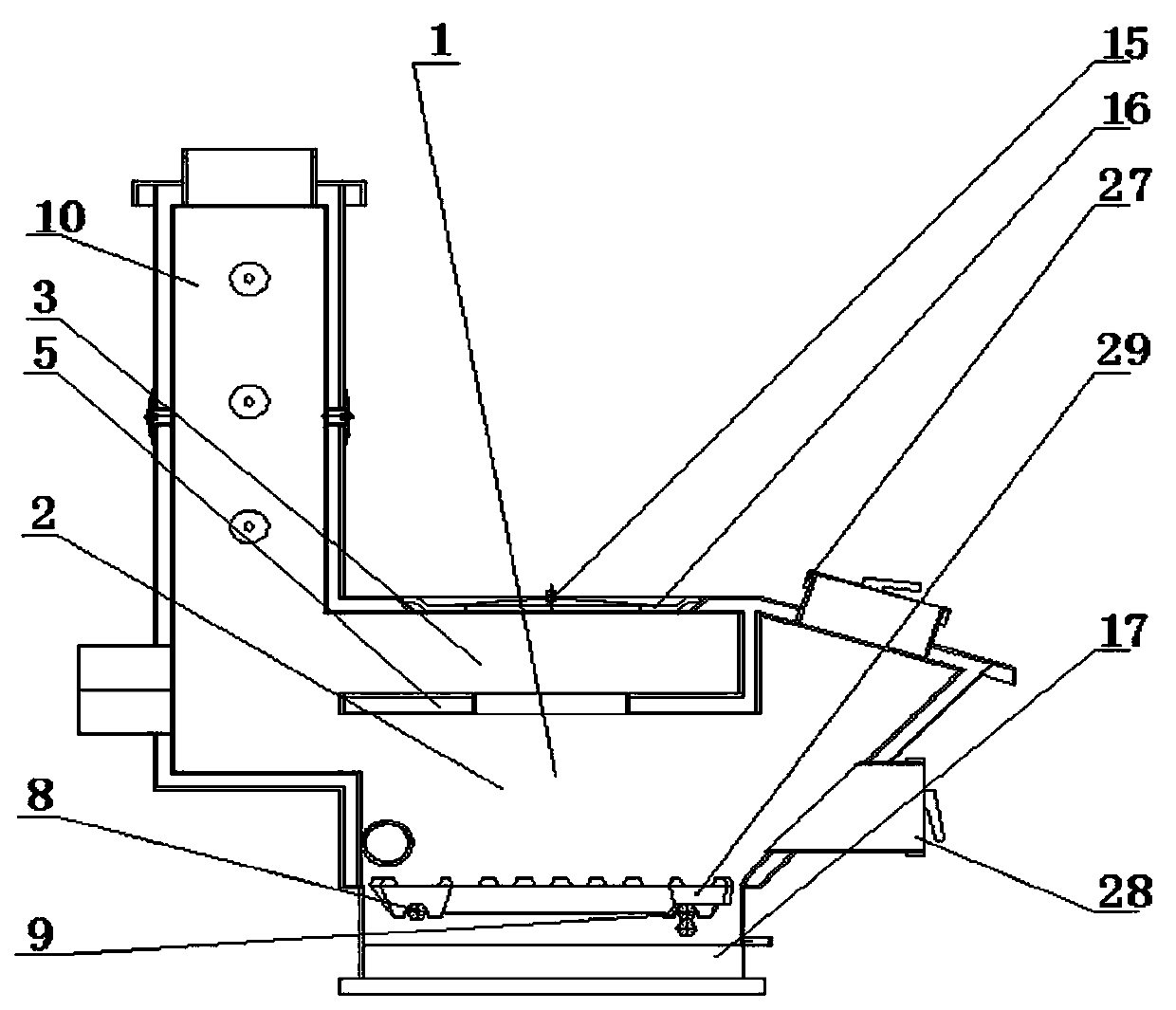
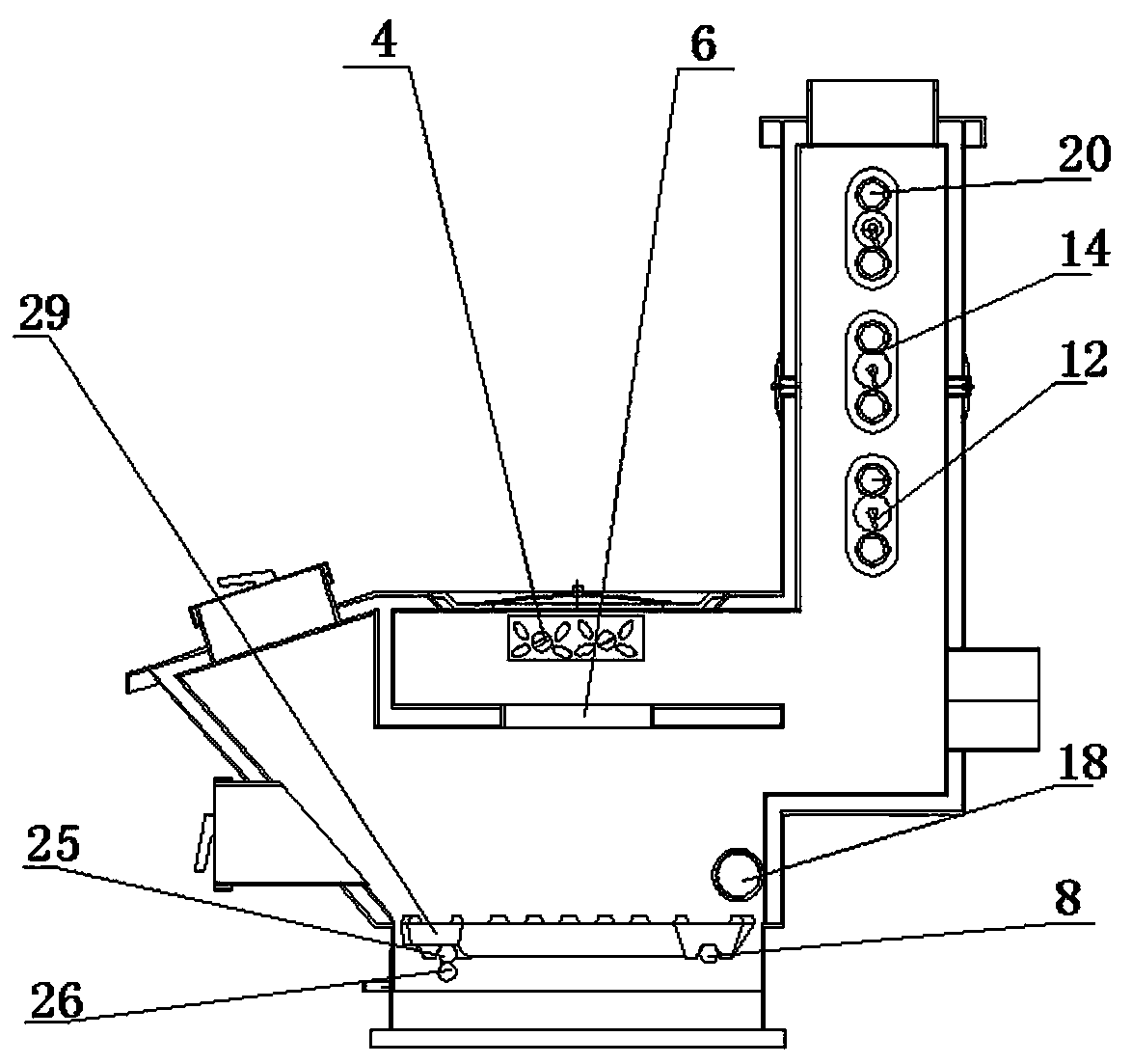
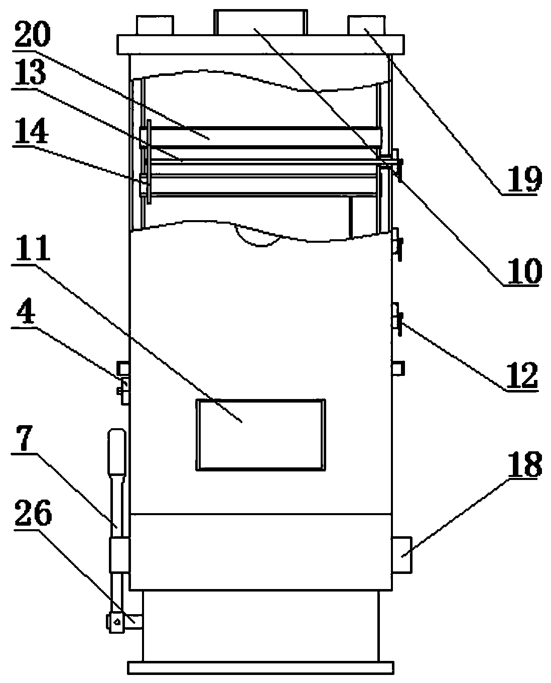
[0028] Such as figure 1 , figure 2 , image 3 , Figure 4 , Figure 5 , Image 6 , Figure 7 , Figure 8 As shown, a multi-functional energy-saving biomass semi-gasification furnace for preventing soot accumulation, including a boiler body 1, a first-floor combustion chamber 2, a second-floor combustion chamber 3, a secondary air damper 4, a grate group 29, and a furnace water-cooled Plate 5, smoke hole 6, grate adjustable wrench 7, fixed shaft 8, movable shaft group 9, main smoke outlet channel 10, furnace door, auxiliary flue 11, pull ring 12, pull rod 13, pull plate 14, furnace cover 15. Furnace ring 16, ash hopper 17, water inlet pipe 18, water outlet pipe 19, heating pipe 20, the combustion chamber 2 of the first layer is arranged at the bottom of the boiler main body 1, and the water cooling plate 5 of the furnace is arranged on the first layer of combustion chamber Above the chamber 2, the middle part of the furnace water cooling plate 5 is provided with a circu...

Embodiment 2

[0030] Such as figure 1 , figure 2 , Figure 7 As shown, the ash receiving hopper 17 is arranged under the grate group 29 and is located at the bottom of the boiler body 1, the furnace ring 16 is arranged on the top of the second-story combustion chamber 3, and the center of the furnace ring 16 is provided with a furnace Cover 15.

Embodiment 3

[0032] Such as figure 1 , figure 2 , image 3 As shown, the left side of the main smoke outlet channel 10 is provided with an auxiliary flue 11, one end of the auxiliary flue 11 communicates with the combustion chamber 2 on the first floor and the combustion chamber 3 on the second floor, and one end extends out of the boiler body 1. The heating tubes 20 are arranged in parallel inside the main smoke outlet channel 10, the number of the heating tubes 20 is six, the pull rings 12 are arranged in parallel at one end outside the main smoke outlet channel 10, and the pull rings 12 The number is 3, one end of the pull rod 13 extends out of the main smoke outlet channel 10 and is connected with the pull ring 12 by a pin, and one end is welded to the pull plate 14 inside the main smoke outlet channel 10, and the pull plate 14 is semi-elliptical shape, the upper and lower ends of the pull plate 14 are provided with through holes in parallel, the size of the through holes matches th...


PUM


Abstract

The invention discloses a multifunctional energy-saving biomass semi-gasification furnace capable of preventing ash accumulation. An auxiliary flue can be used for heating a heated brick bed, and a boiler can also be used as a cooking bench, so that the versatility of the boiler is realized; a heating pipe is arranged in a main smoke outlet channel, and the heating pipe is heated by utilizing thewaste heat of flue gas, so that the waste heat of the flue gas is fully utilized, and the utilization rate of the flue gas of the boiler is improved; a hearth water cooling plate is arranged to form two layers of combustion chambers, so that semi-gasification is achieved in the furnace; a secondary air damper realizes complete gasification and combustion of biomass; a grate group and a grate movable wrench are designed, so that left-right shaking of a strip-shaped grate is realized, the gap is enlarged, and the ash can conveniently fall off and is not accumulated; meanwhile, the contact area with air is increased, the fire stirring effect is started, the fuel is fully combusted, and the fuel resources are saved. The multifunctional biomass semi-gasification furnace can be used for heatinga geothermal heating heated brick bed and can also be used as a cooking bench, the utilization rate of the flue gas of the boiler can be improved, and the biomass fuel is fully combusted.

Description

technical field [0001] The invention relates to the technical field of a biomass gasification furnace, in particular to a multifunctional energy-saving biomass semi-gasification furnace capable of preventing soot accumulation. Background technique [0002] The boiler is a kind of energy conversion equipment. The energy input to the boiler includes chemical energy and electric energy in the fuel, and the boiler outputs steam, high-temperature water or organic heat carrier with a certain amount of heat energy. The original meaning of the pot refers to the water container heated on the fire, and the furnace refers to the place where fuel is burned. The boiler includes two parts: the pot and the furnace. The hot water or steam generated in the boiler can directly provide the required heat energy for industrial production and people's life, and can also be converted into mechanical energy through a steam power device, or converted into electrical energy through a generator. Boil...

Claims


Application Information

Patent Timeline
07 Feb 2020
Publication
CN110762558A
IPC
F24B1/183; F24B1/197; F24B1/193; F24B1/191
CPC
F24B1/183; F24B1/191; F24B1/1915; F24B1/193; F24B1/197
Inventors
付文宏