
CO2 heat pump system

A technology of heat pump system and heat flow path, which is applied in the direction of heating system, hot water central heating system, air conditioning system, etc. It can solve the problem that the heat exchange system cannot meet the demand of hot water and cold water at the same time, and achieve the effect of wide application range

Inactive Publication Date: 2020-02-07
QINGDAO HISENSE HITACHI AIR CONDITIONING SYST
View PDF5 Cites 0 Cited by
  • Summary
  • Abstract
  • Description
  • Claims
  • Application Information

AI Technical Summary

Problems solved by technology

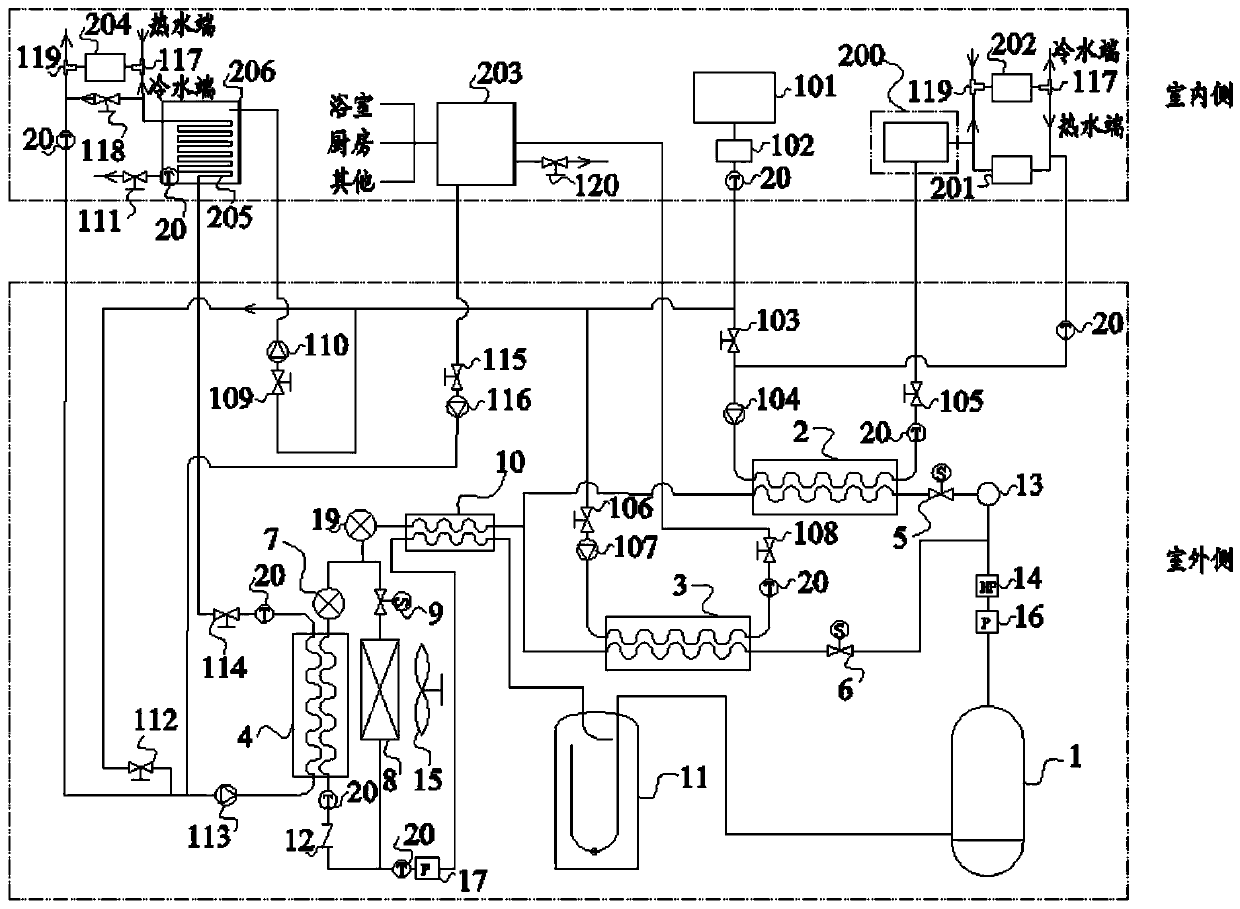
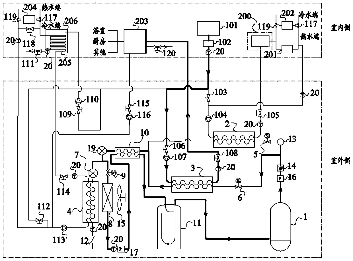
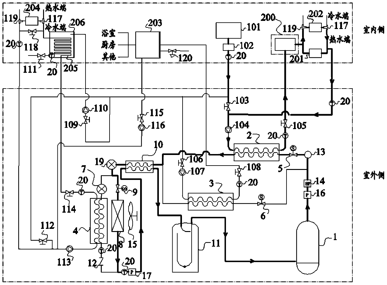
[0004] The present invention provides a CO 2 Heat pump system for solving existing CO 2 The problem that the heat exchange system in the heat pump system cannot meet the needs of hot water and cold water with different water quality requirements at the same time

Method used


Image

  • CO2 heat pump system
  • CO2 heat pump system
  • CO2 heat pump system

Examples


Embodiment Construction

[0025] The following will clearly and completely describe the technical solutions in the embodiments of the present invention with reference to the accompanying drawings in the embodiments of the present invention. Obviously, the described embodiments are only some, not all, embodiments of the present invention. Based on the embodiments of the present invention, all other embodiments obtained by persons of ordinary skill in the art without making creative efforts belong to the protection scope of the present invention.

[0026] In the description of the present invention, it should be noted that unless otherwise specified and limited, the terms "installation", "connection" and "connection" should be understood in a broad sense, for example, it can be a fixed connection or a detachable connection. Connection, or integral connection; it may be mechanical connection; it may be direct connection or indirect connection through an intermediary, and it may be the internal communicatio...


PUM


Abstract

The CO2 heat pump system comprises a CO2 refrigerant loop, a water inlet pipeline and air-conditioning end equipment. The CO2 refrigerant loop comprises a compressor, a first gas cooler, a second gascooler, a throttling device and a water-cooled evaporator. The air-conditioning end equipment comprises a heating device, a first water storage device and a refrigerating device. The first gas coolercomprises a first heat exchange flow path and a second heat exchange flow path; the second gas cooler comprises a third heat exchange flow path and a fourth heat exchange flow path; the water-cooled evaporator comprises a fifth heat exchange flow path and a sixth heat exchange flow path; the first heat exchange flow path and the third heat exchange flow path are connected in parallel between an exhaust port of the compressor and the throttling device, and the fifth heat exchange flow path is connected between the throttling device and an air suction port of the compressor; a water inlet and awater return opening of the heating device are communicated with an outlet and an inlet of the second heat exchange flow path respectively, the first water storage device is communicated with the fourth heat exchange flow path, and a water inlet and a water return opening of the refrigerating device are communicated with an outlet and an inlet of the sixth heat exchange flow path respectively.

Description

technical field [0001] The invention relates to the technical field of heat pumps, in particular to a CO 2 heat pump system. Background technique [0002] With the continuous development of air conditioning technology, heat pump systems have been widely used. The working principle of the heat pump system is a low-temperature and low-pressure liquid refrigerant (such as Freon). First, the refrigerant absorbs heat from a high-temperature heat source (such as normal-temperature air) in the evaporator (such as an air-conditioning indoor unit) and is vaporized into a low-pressure vapor, and then the refrigerant gas It is compressed into a high-temperature and high-pressure vapor in the compressor, and the high-temperature and high-pressure gas is cooled by a low-temperature heat source (such as cooling water) in the condenser to condense into a high-pressure liquid. Then it is throttled by throttling elements (capillary tube, thermal expansion valve, electronic expansion valve,...

Claims


Application Information

Patent Timeline
IPC IPC(8): F24F5/00F24F11/61F24F11/64F24F11/65F24F11/84F24D3/18F24D19/10F24F140/20
CPCF24D3/18F24D19/1015F24F5/0003F24F11/61F24F11/64F24F11/65F24F11/84F24F2140/20
Inventor 周敏赵东方王庆杰高永坤
Owner QINGDAO HISENSE HITACHI AIR CONDITIONING SYST
Learn More