Solid medium heat conduction performance measuring device

A technology of measuring device and solid medium, which is applied in the field of characterization devices of thermal conductivity of materials, can solve the problems of high cost, complicated structure of testing device, complicated operation, etc.

Active Publication Date: 2020-02-07
CHONGQING UNIVERSITY OF SCIENCE AND TECHNOLOGY
View PDF6 Cites 1 Cited by
  • Summary
  • Abstract
  • Description
  • Claims
  • Application Information

AI Technical Summary

Problems solved by technology

However, the use of these methods for testing has the disadvantages of long time consumption and high cost; the structure of the test device is relatively complicated, the cost of equipment is high, and the operation is relatively cumbersome
However, in the process of teaching and testing, sometimes it is only necessary to roughly evaluate the thermal conductivity of materials. At this time, it is obviously not economical to use traditional equipment and methods.
[0003] For different media (solid, liquid, gas), the specific requirements for the measuring device are different. For example, the measuring device for gas and liquid materials has higher sealing performance than solid materials, and the gas is not easy to be completely filled.

Method used


Image

  • Solid medium heat conduction performance measuring device
  • Solid medium heat conduction performance measuring device
  • Solid medium heat conduction performance measuring device

Examples


Embodiment 1

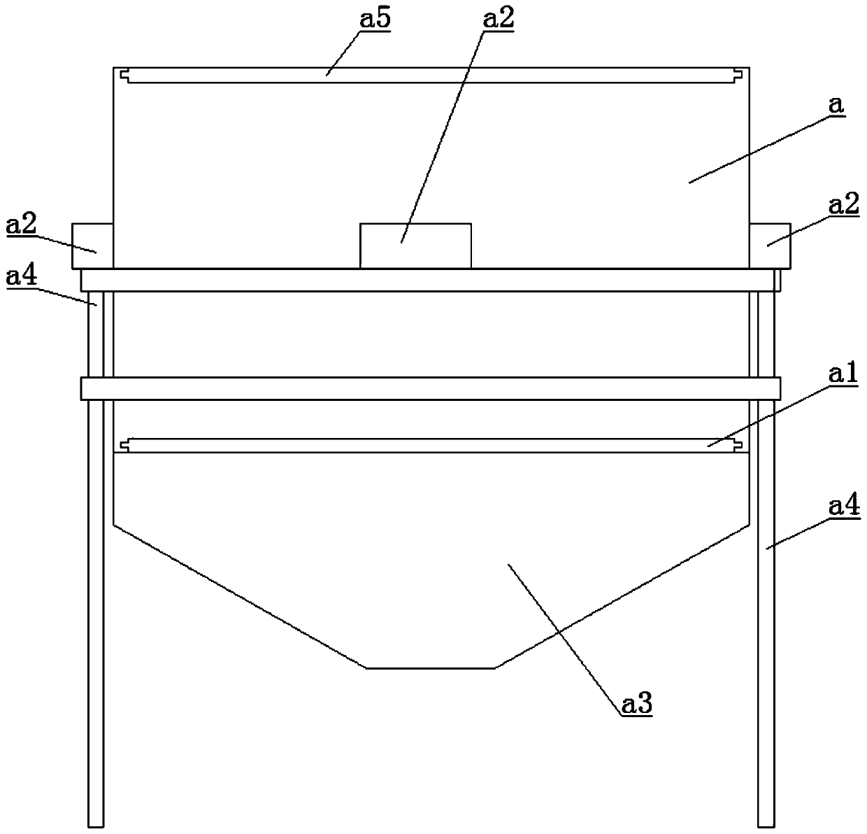
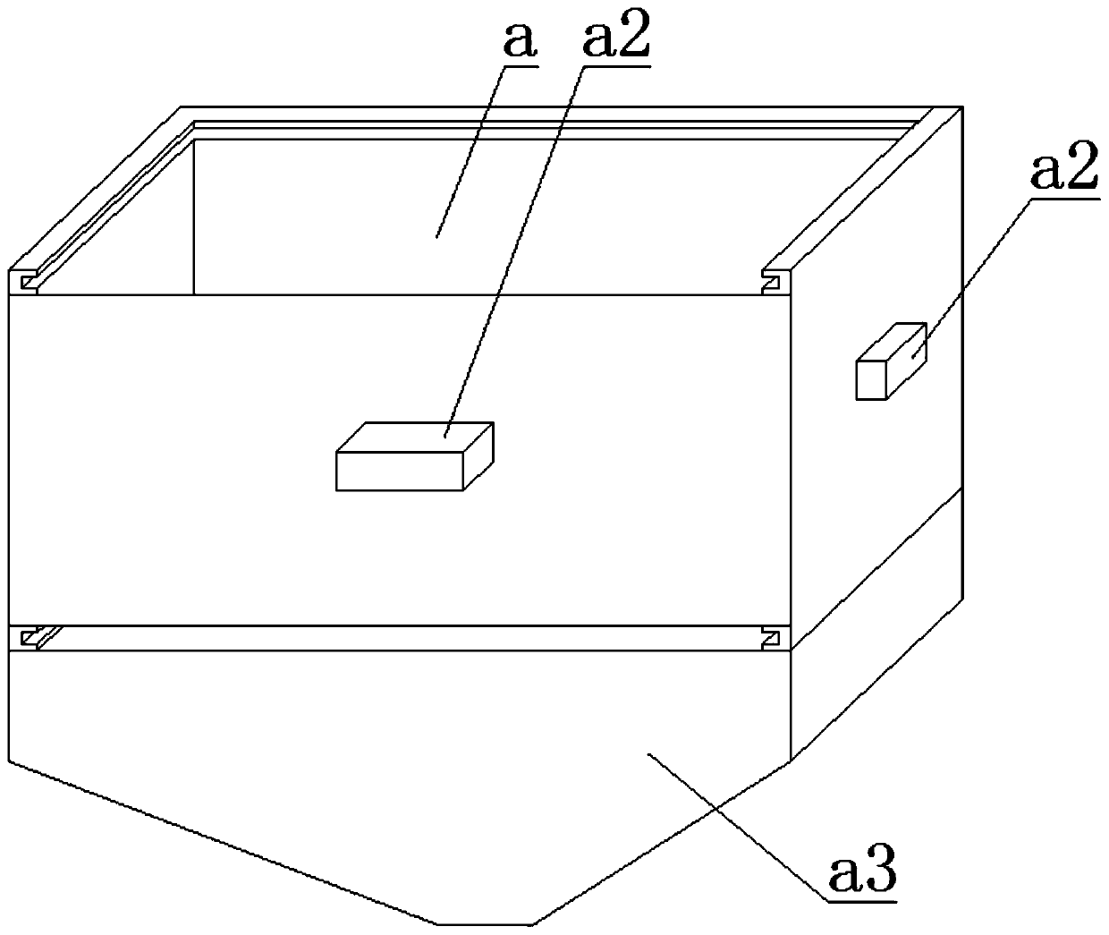
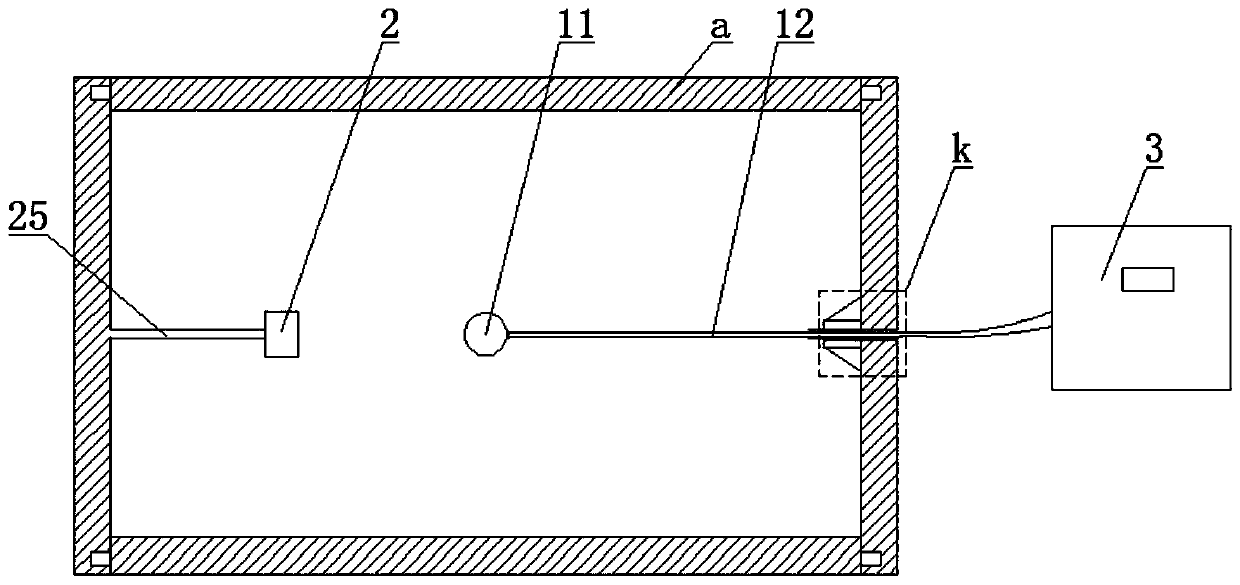
[0054] Such as figure 1 , 2 , 3, a solid medium thermal conductivity measurement device, including a box a and a control display module 3, the box a is provided with a heat source 1 and a first temperature sensing module 2, the heat source 1 and the first temperature sensing module The modules 2 are arranged at intervals, and the heat source 1 and the first temperature sensing module 2 are connected to the control display module 3;

[0055] The top of the box body a is provided with a feed opening, the bottom of the box body a is provided with a discharge opening, the discharge opening is covered with a baffle plate a1, and the feed opening is covered with a shielding plate a5, so A return hopper a3 is provided below the box body a.

[0056] The side wall of the box body a is provided with a material baffle socket corresponding to the material baffle a1, and the inner wall of the box a is provided with a material baffle slot corresponding to the material baffle a1. The mate...

Embodiment 2

[0089] Use the above device to carry out constant temperature heating, and use the specific steps of method ① as follows:

[0090] Step 1, placing the material to be tested and the box a at room temperature (25°C) for at least 24 hours, so that the temperature of the material to be tested and the box a is consistent with room temperature;

[0091] Step 2. At room temperature, heat the heat source 1 to the target temperature and maintain it, and put the material to be tested into the box a from the feeding port within a predetermined time, so that the box a is filled with the material to be tested ;

[0092] Step 3, taking the time when the material to be tested is started to be added as the initial moment, continuously acquire and record the temperature data measured by the first temperature sensing module 2 until the temperature measured by the first temperature sensing module 2 is stable, and plot the temperature - time curve; due to the constant temperature heating, the th...


PUM


Abstract

The invention discloses a solid medium heat conduction performance measuring device which comprises a box body and a control display module. A heat source and a first temperature sensing module are arranged in the box body, the heat source and the first temperature sensing module are arranged at interval, and the heat source and the first temperature sensing module are connected with the control display module. A feeding port is formed in a top of the box body, a discharging port is formed in a bottom of the box body, a material blocking plate covers the discharging port, and a material returning hopper is arranged below the box body. The device has the advantages of simple structure, simple operation, convenience and rapidness, and the heat conduction performance of a material can be simply and rapidly measured and analyzed such that the heat conduction performance of the material is roughly measured.

Description

technical field [0001] The invention relates to a heat conduction measuring device, in particular to a characterization device for the thermal conductivity of a material. Background technique [0002] Thermal conductivity is a measure to characterize the thermal conductivity of materials, which plays an important guiding role in production, life and engineering applications. At present, the methods for testing the thermal conductivity of materials include the heat flow method, the hot plate method, the laser lightning method, the transient plane heat source method, etc., and the test device is adaptable to various test methods. However, the use of these methods for testing has the disadvantages of long time consumption and high cost; the structure of the test device is relatively complicated, the cost of the equipment is high, and the operation is relatively cumbersome. However, in the process of teaching and testing, sometimes it is only necessary to roughly evaluate the t...

Claims


Application Information

Patent Timeline
Patent Type & Authority Applications(China)
IPC IPC(8): G01N25/20G01N25/18
CPCG01N25/18G01N25/20
Inventor 朱礼龙朱光俊张倩影徐屾
Owner CHONGQING UNIVERSITY OF SCIENCE AND TECHNOLOGY
Why Eureka
Try Eureka