
Cassegrain antenna

A Cassegrain antenna and antenna technology, which is applied in the direction of antenna, antenna grounding device, antenna grounding switch structure connection, etc., can solve the problems of complex hyperboloid processing, affecting the standing wave characteristics and errors of the Cassegrain antenna.

Inactive Publication Date: 2020-02-07
NANJING UNIV OF AERONAUTICS & ASTRONAUTICS
View PDF5 Cites 0 Cited by
  • Summary
  • Abstract
  • Description
  • Claims
  • Application Information

AI Technical Summary

Problems solved by technology

Since the feed source of the Cassegrain antenna is facing the secondary reflector, this causes part of the energy to be directly reflected back to the source horn, which affects the standing wave characteristics of the Cassegrain antenna. In the previous design, a hyperboloid was used As a sub-reflector, the vertical incidence of electromagnetic waves is avoided, but the loss cannot be completely avoided. In addition, the processing of the hyperboloid is very complicated, and it is easy to produce large errors.

Method used


Image

  • Cassegrain antenna
  • Cassegrain antenna
  • Cassegrain antenna

Examples


Embodiment 1

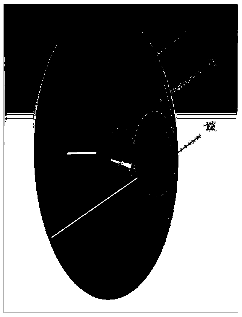
[0035] Embodiment 1, a Cassegrain antenna includes a feed antenna 11 , a main reflector 13 , a secondary reflector 12 and a fixing device 15 for the main and secondary reflectors; wherein the feed antenna 11 is a horn antenna.

[0036] Described main reflecting surface 13, its parabolic equation is: y 2 =4f m x, the parabola is formed by rotating a parabola around the x-axis, and the diameter of the mouth is 130-180mm. In the form of a parabola, the focusing characteristics of the parabola are mainly used, so that the energy of the Cassegrain antenna is concentrated at the focus of the parabola, and the radiated energy of the measured target is enhanced.

[0037] The secondary reflection surface 12 adopts a hyperboloid form, and its hyperbolic equation is: The hyperboloid is formed by rotating the hyperboloid around the x-axis, and the diameter of the mouth is 15-25mm. One focus of the hyperboloid coincides with the focus of the parabola, and the feed antenna is located on ...

Embodiment 2

[0042] Embodiment 2, the sub-reflecting surface 12 described in Embodiment 1 adopts a conical frustum 31, and the conical frustum is a curve y=0.5e 0.03*x +0.02x, formed by rotating 360° around the y-axis, which can reduce the standing wave coefficient of the antenna. Its position is located at the midpoint between the feed antenna and the focus of the main reflector 13, and the electromagnetic wave is radiated from the conical horn 11 to the secondary reflection On the surface, because it has a certain angle to the frustum 31, it can avoid the vertical reflection of electromagnetic waves, and can reduce the return loss of the antenna to less than 20dB. Figure 12 shown.

Embodiment 3

[0043] Embodiment 3, the sub-reflector 12 described in embodiment 1 adopts a circular metal plate 41 with a radius of 15mm-25mm, its position is located at the midpoint of the feed antenna and the focus of the main reflector 13, and the processing is simple. The curved surface greatly reduces the difficulty of processing and saves costs. The antenna characteristics will be slightly reduced, but it is still acceptable. The return loss of the antenna is less than 18dB. Figure 13 shown.


PUM


Abstract

The invention discloses a Cassegrain antenna. The Cassegrain antenna comprises a feed antenna (11), a primary reflecting surface (13), a secondary reflecting surface (12) and a primary and secondary reflecting surface fixing device (15); the feed antenna (11) is a horn antenna; the primary reflecting surface (13) adopts a paraboloidal form, and a round hole with the radius is about equal to a working wavelength 2.5-4 mm is formed in the center of the secondary reflecting surface (12), so standing wave characteristic of the antenna can be improved efficiently. In addition, energy directly radiated through the round hole can make up reflection energy lost by holing, so the gain characteristic is also improved to a certain extent. The Cassegrain antenna further comprises a quarter wavelengthchoke groove (14) which is located at the edge of the primary reflecting surface and has the width and the depth being a quarter of the central working wavelength. The quarter wavelength choke groovecan efficiently reduce diffraction of electromagnetic waves and has a good inhibiting effect on the electric level of a minor lobe of the antenna; and the antenna has the working efficiency of 75-110GHz.

Description

technical field [0001] The invention relates to an antenna. Background technique [0002] Remote sensing technology is a technology that collects electromagnetic radiation information of ground objects and targets from artificial satellites, aircraft or other aircraft, and identifies the earth's environment and resources. In remote sensing detection, the Cassegrain antenna is the most commonly used one, because of its narrow beam, high gain, and low return loss, it can well meet the needs of remote sensing detection. The Cassegrain antenna is a double-reflector antenna, which consists of a feed antenna, a main reflector and a sub-reflector, and a fixing device for the main and sub-reflectors. Located at another virtual focal point of the hyperboloid, the electromagnetic wave radiates on the paraboloid, reflects on the hyperboloid, reflects again, and focuses on the conical horn. Since the feed source of the Cassegrain antenna is facing the secondary reflector, this causes ...

Claims


Application Information

Patent Timeline
Patent Type & Authority Applications(China)
IPC IPC(8): H01Q1/36H01Q1/48H01Q1/50H01Q15/14H01Q5/20
CPCH01Q1/36H01Q1/48H01Q1/50H01Q15/14H01Q5/20
Inventor 刘可
Owner NANJING UNIV OF AERONAUTICS & ASTRONAUTICS
Learn More