Bearing ring grinding tool and method

A bearing ring and grinding technology, which is applied in the field of bearing manufacturing, can solve problems such as unstable part processing quality, long tooling adjustment time, and process parameters that cannot be solidified, so as to improve product processing efficiency, improve grinding quality, and save tooling The effect of adjusting the time

Inactive Publication Date: 2020-02-11
AVIC HARBIN BEARING
View PDF4 Cites 3 Cited by
  • Summary
  • Abstract
  • Description
  • Claims
  • Application Information

AI Technical Summary

Problems solved by technology

[0004] In order to solve the problems that the existing process parameters cannot be solidified during the grinding process of the inner surface of the bearing ring, the tooling adjustment time is long, and the processing quality of the parts is unstable, the present invention further provides a bearing ring grinding tool and method

Method used


Image

  • Bearing ring grinding tool and method
  • Bearing ring grinding tool and method
  • Bearing ring grinding tool and method

Examples


specific Embodiment approach 1

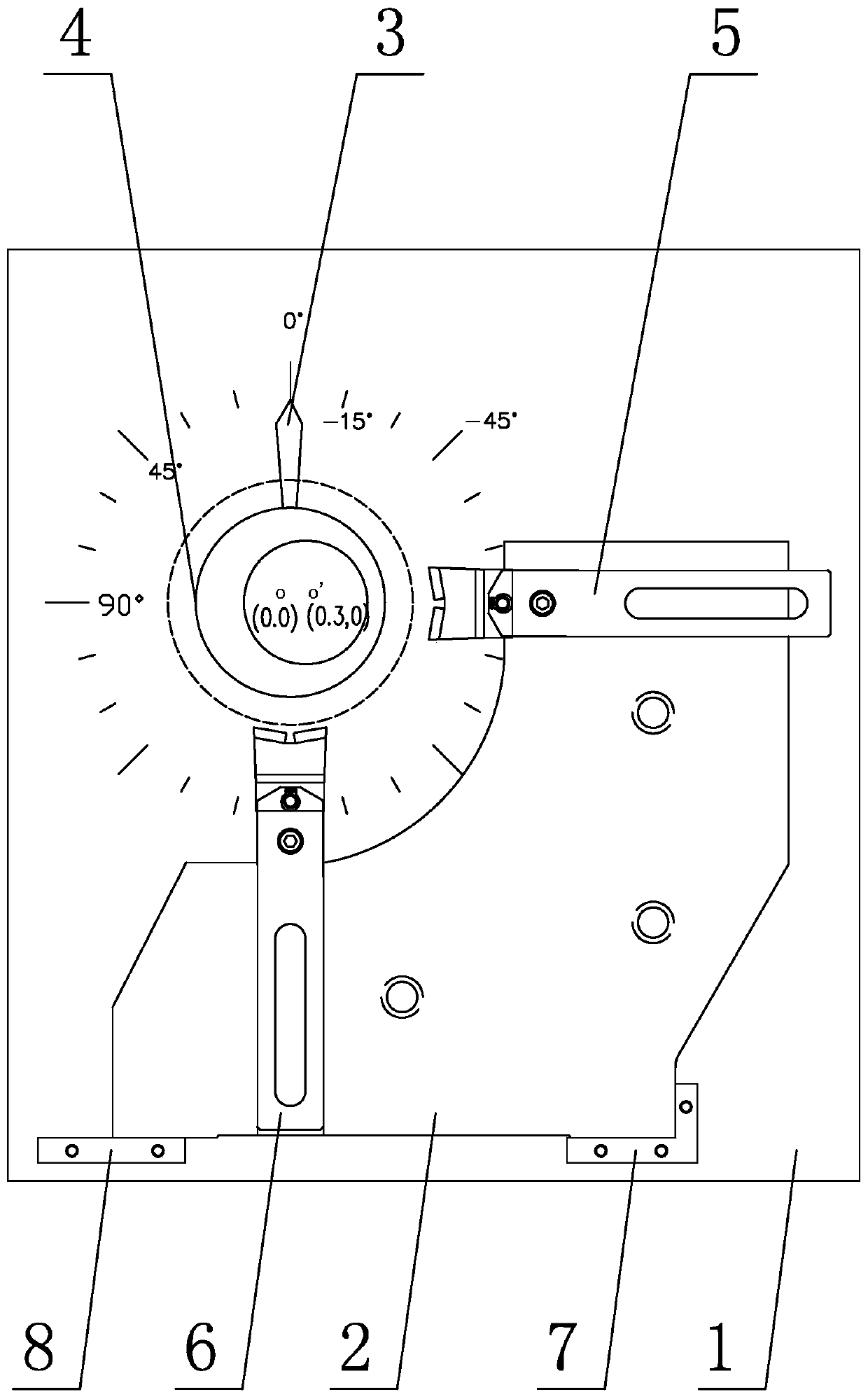
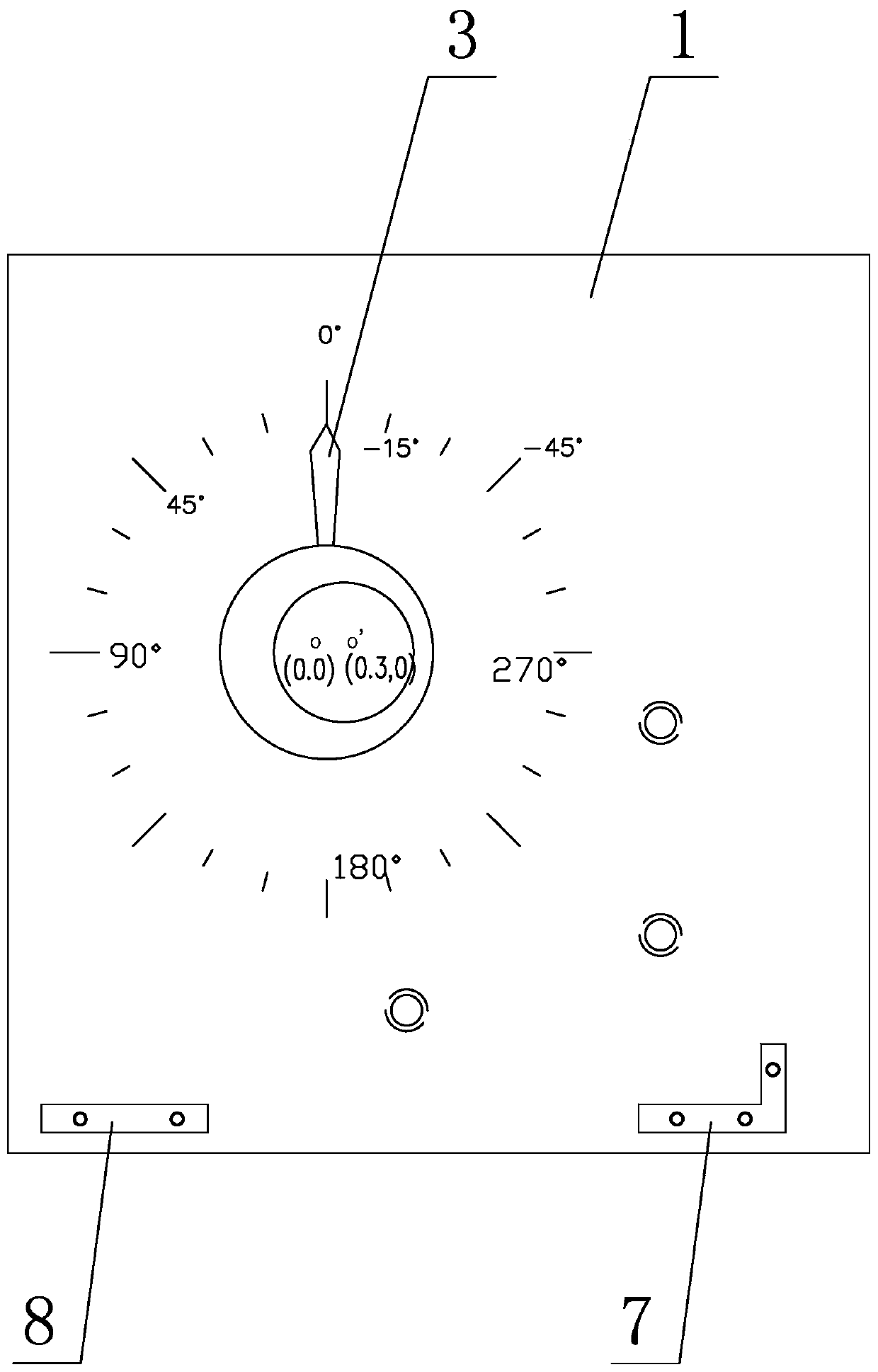
[0043] Specific implementation mode one: combine Figure 1 to Figure 6Describe this embodiment, a bearing ring grinding tool of this embodiment, which includes a positioning reference scale panel 1, a fulcrum seat 2, an adjustment knob 3, an axle 4, a horizontal fulcrum 5, a vertical fulcrum 6, and a main positioning pin 7 and auxiliary positioning pin 8, a dial is provided on the end face of the positioning reference scale panel 1, and the positioning reference scale panel 1 in the center of the dial is provided with a first assembly hole matched with the adjustment knob 3, and the fulcrum seat 2 passes through the main The positioning pin 7 and the auxiliary positioning pin 8 are fixed on the positioning reference scale panel 1, and the adjustment knob 3 includes a first cylinder 3-1, a second cylinder 3-2 and a pointer 3-3, and the second cylinder 3-2 is eccentrically arranged on the second cylinder 3-2. On the end face of a cylinder 3-1, the pointer 3-3 is set on the outer...

specific Embodiment approach 2

[0047] Specific implementation mode two: combination Figure 8 to Figure 11 , Figure 13 to Figure 15 Describe this embodiment, the structure of horizontal fulcrum 5 of this embodiment and vertical fulcrum 6 is identical, and horizontal fulcrum 5 comprises horizontal fulcrum rod 5-1, horizontal rotary shaft 5-3, horizontal fulcrum head 5-4 and two horizontal shafts. The retaining ring 5-5, the upper end surface of the horizontal fulcrum rod 5-1 is provided with a positioning groove 5-1-1 along the vertical direction, and the two side walls of the positioning groove 5-1-1 are provided with a horizontal axis of rotation 5 along the horizontal direction. -3 matched first shaft hole 5-1-2, the lower part of the horizontal support head 5-4 is inserted in the positioning groove 5-1-1, and the horizontal support head 5-4 is provided with a horizontal return along the horizontal direction. The second shaft hole 5-4-3 matched with the rotating shaft 5-3, the horizontal fulcrum head 5-...

specific Embodiment approach 3

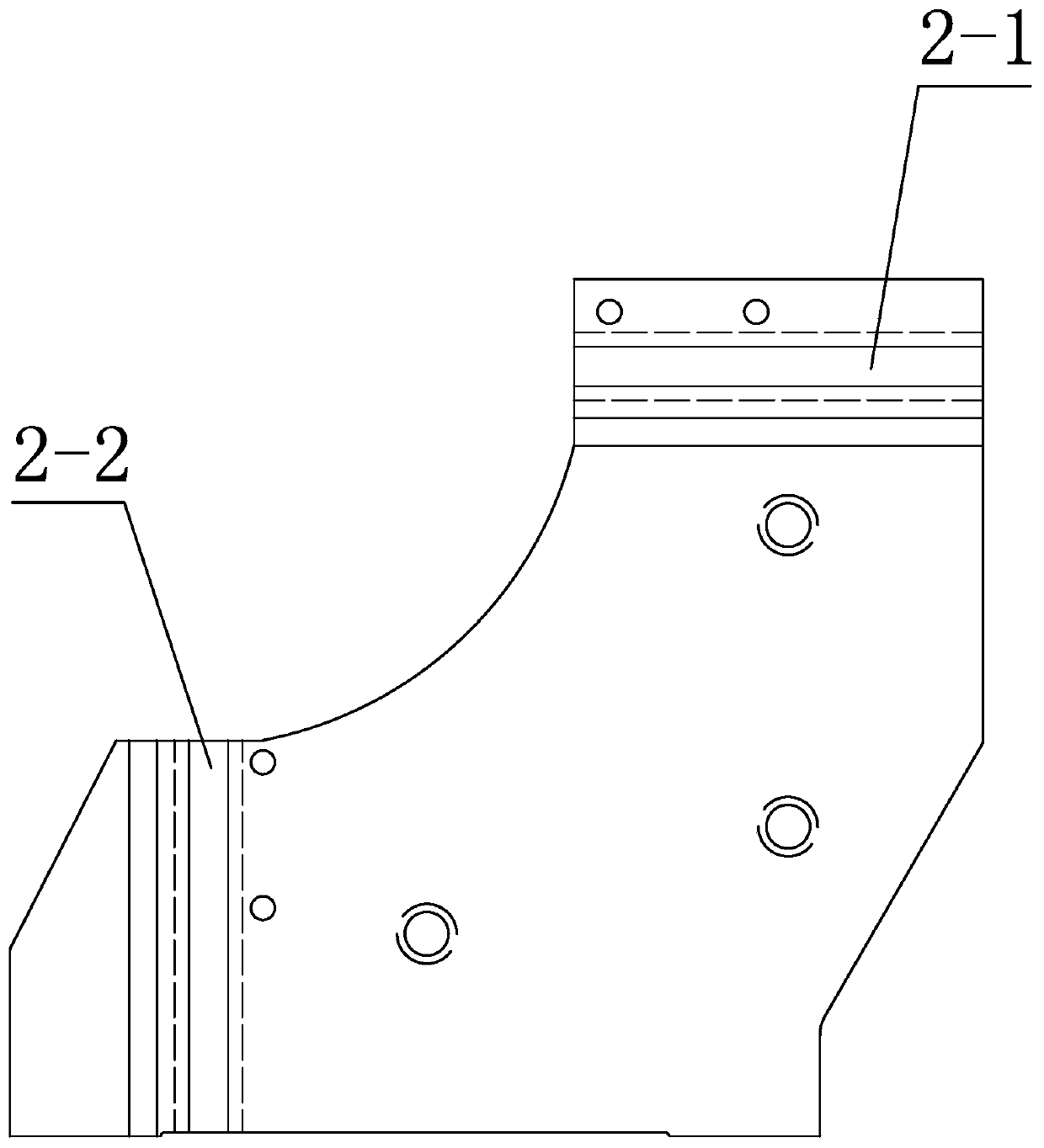
[0048] Specific implementation mode three: combination Figure 8 to Figure 13 To illustrate this embodiment, the horizontal fulcrum 5 of this embodiment also includes a hexagon socket head cap screw 5-2, and the bottom surface of the positioning groove 5-1-1 is also provided with a locking groove 5-1-3 along the vertical direction, and the lock The two side walls of the tight groove 5-1-3 are provided with the first threaded hole 5-1-4 matched with the hexagon socket head screw 5-2 along the horizontal direction, and the horizontal support head 5-4 passes through the hexagon socket head screw 5-2 is fixedly connected with horizontal fulcrum rod 5-1. Set in this way, when the horizontal fulcrum 5 slides to the outer circle of the opposite axle 4 along the horizontal fulcrum slot 2-1, after the horizontal fulcrum 5 is in close contact with the opposite axle 4, screw the hexagon socket head cap screw 5-2 on the first thread In the hole 5-1-4, the horizontal fulcrum head 5-4 is l...


PUM


Abstract

The invention discloses a bearing ring grinding tool and a method, and relates to the field of bearing manufacturing. The bearing ring grinding tool and the method solve the problems in the prior artthat when the inner surface of a bearing ring is ground, process parameters cannot be fixed, the tool adjustment time is long, and the part machining quality is unstable. The end face of a positioningdatum reference scale panel is provided with a scale disc, a pivot base is fixed to the positioning datum reference scale panel through a main positioning pin and an auxiliary positioning pin, and anadjustment knob comprises a first cylinder, a second cylinder and a pointer; the second cylinder is eccentrically arranged on the end face of the first cylinder, the pointer is arranged on the outercircumference of the first cylinder, the adjustment knob is installed on the positioning datum reference scale panel, a centering shaft is installed on the adjustment knob, the outer diameter of the centering shaft is the same as the size of the outer circle of a machined ring, a horizontal pivot is slidably installed in a horizontal pivot slot, and a vertical pivot is slidably installed in a vertical pivot slot. The bearing ring grinding tool and the method are used for stabilizing and improving the grinding quality of the inner surface of the ring.

Description

technical field [0001] The invention relates to the field of bearing manufacturing, in particular to a bearing ring grinding tool and method. Background technique [0002] The stability of the grinding quality of the bearing ring is the reliability guarantee of the grinding process, and the solidification of the grinding process parameters has always been a difficult problem in the processing of bearing parts. The adjustment level of the grinding tooling directly affects the grinding quality of the bearing. Usually, when grinding the outer surface or inner surface of the ferrule, its end face and outer diameter surface are used as the processing reference. For ferrules with different sizes and structures, the operator can only manually adjust the fulcrum angle and ferrule eccentricity when processing different ferrules. Generally, it is necessary to adjust the fulcrum and eccentricity several times until the grinding quality meets the process requirements. Such a processing...

Claims


Application Information

Patent Timeline
Patent Type & Authority Applications(China)
IPC IPC(8): B24B5/35B24B5/36B24B47/22
CPCB24B5/35B24B5/36B24B47/22
Inventor 刘明刘明阳吴玉成胡北刘泓硕张振明高宝龙李浩玮刘凯胡翔姜佳良马文良辛凯林康
Owner AVIC HARBIN BEARING
Why Eureka
Try Eureka