Method for preventing hole collapse of drilling pile by automatic ejecting steel protection cylinder

A technology of automatic pop-up and steel casing, applied in sheet pile wall, construction, infrastructure engineering, etc., can solve the problems of reduced water head pressure, prone to collapse holes, reduced mud specific gravity, etc. Precise control, material saving effect

Inactive Publication Date: 2020-02-11
CHINA RAILWAY NO 10 ENG GRP NO 1 ENG CO LTD
View PDF5 Cites 3 Cited by
  • Summary
  • Abstract
  • Description
  • Claims
  • Application Information

AI Technical Summary

Problems solved by technology

Some hole collapse problems can be prevented by increasing the specific gravity of the mud, increasing the water head height, reducing the drilling speed, and lengthening the casing. However, the effect is not obvious when the hole collapse is deep and the geology is particularly loose. After the hole is formed, the specific gravity of the mud is reduced after the hole cleaning process, the storage time is long, and the problem of hole collapse is still prone to occur when the steel cage is lowered to scratch the hole wall
[0003] In the construction of bored piles in loose ground, measures such as increasing the proportion of mud, increasing the height of the water head, and reducing the drilling speed are often used to prevent hole...

Method used


Image

  • Method for preventing hole collapse of drilling pile by automatic ejecting steel protection cylinder
  • Method for preventing hole collapse of drilling pile by automatic ejecting steel protection cylinder
  • Method for preventing hole collapse of drilling pile by automatic ejecting steel protection cylinder

Examples


Embodiment Construction

[0027] The present invention will be further described below in conjunction with accompanying drawing by non-limiting embodiment:

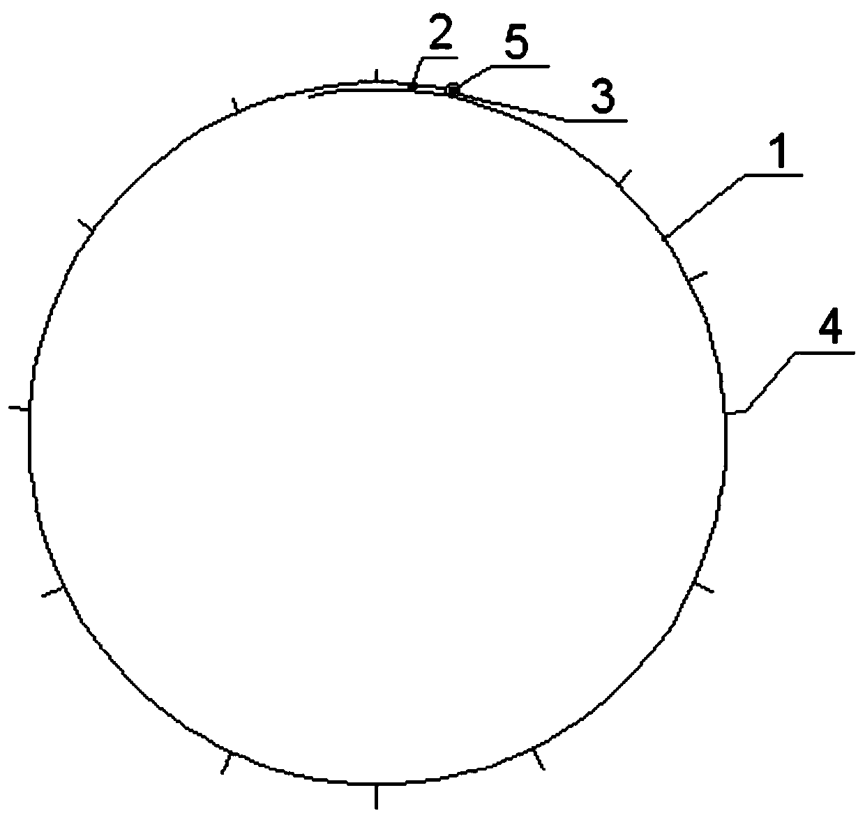
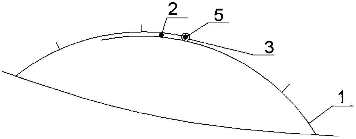
[0028] A method for automatically bouncing steel casings to prevent bored piles from collapsing, which involves lowering the steel casings that can be automatically bouncing after being rolled to the position to be supported in the bored piles, and then bouncing the steel casings , the outer wall of the steel casing is attached to the hole wall of the bored pile and fixed to form a support.

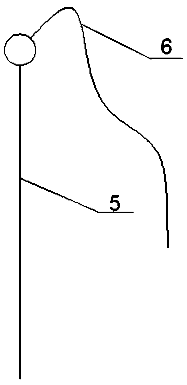
[0029]As shown in the accompanying drawings, the device for preventing bored piles from collapsing in order to realize the above method is as follows: it includes a steel casing device that can automatically bounce, and a steel casing hanging device. The steel casing device that can be automatically bounced off includes a cylindrical steel casing 1 made of rolled steel sheets. A steel bar with a diameter of 6 mm is welded along the height direction of the st...


PUM


Abstract

The invention discloses a method for preventing hole collapse of a drilling pile by automatic ejecting a steel protection cylinder. The method is characterized in that the steel protection cylinder which can be automatically ejected after being rolled is lowered into a to-be-supported position in the drilling pile, so that the steel protection cylinder is ejected, and the outer wall of the steel protection cylinder and the hole wall of the drilling pile are bonded and fixed to form a support. According to the method, a steel protection cylinder device capable of being automatically ejected anda steel protection cylinder lifting and placing device are used for construction, the steel protection cylinder device capable of being automatically ejected comprises the cylindrical steel protection cylinder formed by rolling a steel plate, the two ends of the steel plate are in lap joint to form handers, a steel bar is welded to the inner side face of the hander, located on the outer side, ofthe steel protection cylinder in the height direction of the steel protection cylinder to form a retraction clamping groove, a plurality of nuts are arranged at the handers position of the steel protection cylinder, the handers of the steel protection cylinder are connected through bolts inserted in the nuts, the top ends of the bolts are connected with connecting ropes, a plurality of steel bar heads are fixedly connected to the outer side surface of the steel protection cylinder, and the steel protection cylinder can be sleeved on the steel protection cylinder lifting device.

Description

technical field [0001] The invention relates to a method for preventing bored piles from collapsing, and belongs to the technical field of engineering construction. Background technique [0002] During the construction of engineering bored piles, if encountering unfavorable strata such as sand, pebble soil and other strata, it often causes different degrees of hole collapse. Some hole collapse problems can be prevented by increasing the specific gravity of the mud, increasing the water head height, reducing the drilling speed, and lengthening the casing. However, the effect is not obvious when the hole collapse is deep and the geology is particularly loose. After the hole is formed, the specific gravity of the mud is reduced through the hole cleaning process, the storage time is long, and the problem of hole collapse is still prone to occur when the steel cage is lowered to scratch the hole wall. [0003] In the construction of bored piles in loose ground, measures such as ...

Claims


Application Information

Patent Timeline
IPC IPC(8): E02D13/00E02D5/38
CPCE02D5/38E02D13/00
Inventor 陈聪井永军周建明黄清华荆剑姚德臣李如杰尚明徐延召
Owner CHINA RAILWAY NO 10 ENG GRP NO 1 ENG CO LTD
Why Eureka
Try Eureka