Dry type connection system of a prefabricated type wood-concrete composite structure

A combined structure and prefabricated assembly technology, which is applied in the direction of erecting/assembling bridges, building components, building structures, etc., can solve the problems of low construction efficiency and achieve the effects of improving appearance, reducing impact, and good fire resistance

Pending Publication Date: 2020-02-11
NANJING UNIV OF TECH
0 Cites 3 Cited by

AI-Extracted Technical Summary

Problems solved by technology

Because of wet joints, semi-prefabricated "wet" connections mainly have problems s...

Abstract

The invention discloses a dry type connection system of a prefabricated type wood-concrete composite structure. The dry type connection system includes wooden beams, concrete slabs and dry type shearconnection pieces. Each dry type shear connection piece includes an embedded steel plate and assembling screws. In-plate steel bars of the concrete slabs pass through pre-opened holes of the embeddedsteel plates, the embedded steel plates are positioned when concrete is poured, and strengthening and anchoring are carried out; the wooden beams are arranged between the two embedded steel plates, grooves with the depth equal to the thickness of the embedded steel plates are formed in the positions, in contact with the steel plates, of the wooden beams, exposed parts of the embedded steel platesare inserted into the grooves of the wooden beams during field assembly, the screws are used for connecting the concrete slabs where the steel plates are embedded and the wooden beams, and assemblingof the wood-concrete composite structure is realized. By means of the dry type connection system, the wooden beams and the concrete slabs are prefabricated in a plant and spliced on a construction site, the on-site form erecting processes are reduced, and the concrete curing time is shortened.

Application Domain

Technology Topic

Image

  • Dry type connection system of a prefabricated type wood-concrete composite structure
  • Dry type connection system of a prefabricated type wood-concrete composite structure
  • Dry type connection system of a prefabricated type wood-concrete composite structure

Examples

  • Experimental program(1)

Example Embodiment

[0022] The present invention will be further described below in conjunction with the drawings and specific embodiments.
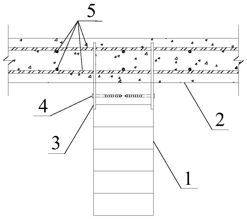
[0023] Such as Figure 1-5 As shown, a "dry" connection system of a prefabricated wood-concrete composite structure includes a wooden beam 1, a concrete slab 2 and a "dry" shear connector. The wooden beam 1 is connected by a "dry" shear The part is connected with the concrete slab 2; the "dry" shear connector includes a steel plate 3 and an anchor screw 4.
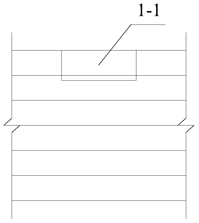
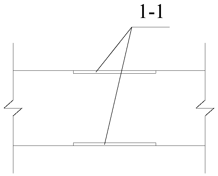
[0024] The steel plate 3 includes the non-embedded part of the steel plate 3-1, the anchor screw hole 3-2, the embedded part of the steel plate 3-3, and the reinforcement hole 3-4. The steel plate 3-3 of the pre-embedded part is embedded in the concrete slab 2, and the in-slab reinforcement 5 in the concrete slab 2 penetrates the reinforcing steel hole 3-4 in the steel plate 3. When pouring the precast concrete slab, in order to ensure two The accuracy of the distance between the steel plates 3 can be temporarily nailed between the anchor screw holes 3-2 of the two steel plates 3 with a wooden block of the same width as the wooden beam with lateral grooves, and the temporary wood can be removed when assembled on site. Perform assembly after block. At the connection between the wooden beam 1 and the shear connector, grooves 1-1 of the same size as the steel plate 3-1 of the non-embedded part are processed on both sides of the wooden beam 1, and the depth of the groove 1-1 should be the same as that of the steel plate 3-1. The thickness of 3 is the same. When the wooden beam 1 is assembled with the concrete slab 2, the wooden beam 1 is placed between the two steel plates 3, and the non-pre-embedded part of the steel plate 3-1 is inserted into the groove 1-1 of the wooden beam 1, and 4 pairs of anchor screws are used. The wooden beam 1 and the concrete slab 2 are fixed. The rebar holes 3-4 and anchor screw holes 3-2 are respectively multiple, and they are all arranged horizontally and evenly. The diameter of the anchor screw hole 3-2 on the non-embedded part of the steel plate 3-1 is 0.5mm larger than the diameter of the anchor screw 4, and the pre-opened reinforcement hole 3 on the steel plate 3-3 of the embedded part The diameter of -4 should be 1mm larger than the diameter of the ribs 5 in the plate to facilitate the smooth passage of the anchor screws 4 and the ribs 5 in the plate.
[0025] The embodiments of the present invention are described in detail above with reference to the accompanying drawings, but the present invention is not limited to the described embodiments. For those of ordinary skill in the art, within the scope of the principles and technical ideas of the present invention, various changes, modifications, replacements and modifications to these embodiments still fall within the protection scope of the present invention.

PUM

no PUM

Description & Claims & Application Information

We can also present the details of the Description, Claims and Application information to help users get a comprehensive understanding of the technical details of the patent, such as background art, summary of invention, brief description of drawings, description of embodiments, and other original content. On the other hand, users can also determine the specific scope of protection of the technology through the list of claims; as well as understand the changes in the life cycle of the technology with the presentation of the patent timeline. Login to view more.

Similar technology patents

Inorganic phosphorescent article and method for making same

InactiveUS20100285284A1Pronounced and sustained phosphorescent effectImprove aestheticsDecorative surface effectsDuplicating/marking methodsZinc sulfideEmergency light
Owner:LACOURSE BRIAN C

Surface treatment method of mirror stainless steel objects

InactiveCN102259287AImprove aestheticsAvoid the problem of overthrow deformation and sinkingPlane surface grinding machinesSurface grindingSandpaper
Owner:李俊霈

Classification and recommendation of technical efficacy words

Why Eureka
Try Eureka