
Drilling speed increase tool capable of forming periodic drill string axial creeping and drilling pressure fluctuation

A periodic, drill string technology, applied in drilling equipment, driving devices for drilling in wellbore, earth-moving drilling, etc. speed and the effectiveness of WOB transfer, etc.

Pending Publication Date: 2020-02-11
SINOPEC SSC +2
View PDF0 Cites 0 Cited by
  • Summary
  • Abstract
  • Description
  • Claims
  • Application Information

AI Technical Summary

Problems solved by technology

[0002] In recent years, the structure complexity of oil and gas wells in oil and gas drilling projects has gradually increased. The proportion of complex structure wells such as deep wells, ultra-deep wells, long horizontal wells, and multi-branch wells in the actual production process is increasing. The drilling depth Hard rock formations and well wall friction in deep wells due to the increase in the complexity of the wellbore structure have reduced the ROP of rock-breaking drilling and the effectiveness of WOB transmission, and the requirements for drilling methods and technology are also increasing. The traditional impact drilling speed-increasing tools such as hydraulic impactor, torsion impactor, down-the-hole hammer and other tools convert the kinetic energy of the drilling working medium into the hard impact energy of the impact hammer and anvil to generate a certain frequency It is difficult to solve the fatigue failure problem caused by the hard impact on the metal surface by means of rock-breaking impact energy, which makes it difficult to improve the working life of this type of tool, and cannot solve the problem of increased friction in deep wells, horizontal wells and other formations
To this end, scholars at home and abroad have proposed a large number of solutions, among which the most effective and widely used tool is the hydraulic oscillator (the main representative is the NOV hydraulic oscillator), which can generate axial peristalsis with a certain period , can effectively solve the problem of formation friction resistance, but it can only effectively transmit the WOB, and cannot produce periodic fluctuations of the WOB, and the improvement of the ROP is not obvious

Method used


Image

  • Drilling speed increase tool capable of forming periodic drill string axial creeping and drilling pressure fluctuation
  • Drilling speed increase tool capable of forming periodic drill string axial creeping and drilling pressure fluctuation
  • Drilling speed increase tool capable of forming periodic drill string axial creeping and drilling pressure fluctuation

Examples


Embodiment 1

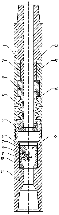
[0027] see figure 1 As shown, the drilling speed-up tool that can form periodic drill string axial creep and WOB fluctuations includes an upper joint 1, a casing 2, and a lower joint 11;

[0028] The upper joint 1 is set on the upper end of the shell 2, the upper joint 1 is used to connect with the upper drill string, and the lower joint 11 is threadedly connected to the lower end of the shell 2, wherein the cavity of the shell 2 is provided with a stepped shaft 3, and the lower joint The upper end in the cavity of 11 is connected with the bearing ring 5 in sliding seal.

[0029] The upper end of the stepped shaft 3 is threadedly connected to the lower end of the upper joint 1, and the lower end of the stepped shaft 3 is threadedly connected to the pressure ring 5, and the upper joint 1, the stepped shaft 3, the pressure ring 5 and the lower joint 11 form a connected flow channel .

[0030] The middle part of the outer periphery of the step shaft 3 is covered with a disc spr...

Embodiment 2

[0048] This embodiment is optimized on the basis of embodiment 1, specifically:

[0049] see figure 1 As shown, the inner diameter of the upper limit step 13 of the housing 2 is smaller than the diameter of the upper end of the stepped shaft 3;

[0050] The inner diameter of the upper limit step 13 of the housing 2 is smaller than the diameter of the middle part of the upper joint 1 .

[0051] The axial movement of the step shaft 3 and the upper joint 1 is limited by the limit step 13. On the one hand, a step fit is formed to effectively prevent the bottom hole drill bit connected to the lower end from falling, and on the other hand, it can prevent excessive WOB in the upper part. Disc spring group 4 is crushed, thereby can play a protective role.

Embodiment 3

[0053] This embodiment is optimized on the basis of embodiment 1, specifically

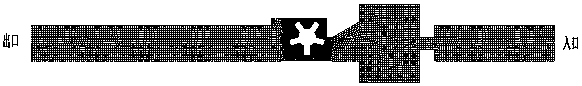
[0054] see figure 1 As shown, the eccentric flow channel 15 on the impeller guide sleeve 7 is closed;

[0055] By designing the eccentric flow channel 15 into a closed structure, the drilling circulating medium can be gradually supercharged after flowing through the eccentric flow channel 15 of the impeller guide sleeve 7, and the pressurized drilling circulating medium has a greater impact force The driving impeller 9 forms stronger pulses.


PUM


Abstract

The invention discloses a drilling speed increase tool capable of forming periodic drill string axial creeping and drilling pressure fluctuation. The drilling speed increase tool comprises a shell, the upper end of the shell is sleeved with an upper joint, the lower end of the shell is connected with a lower joint, and a pressure bearing ring is in sliding and sealed connection with the upper endin a cavity of the lower joint; a stepped shaft is arranged in a cavity of the shell, the upper end of the stepped shaft is connected to the lower end of the upper joint, the lower end of the steppedshaft is connected to the pressure bearing ring, the periphery of the stepped shaft is sleeved with a disc spring set, and the two ends of the disc spring set abut against the outer side step face ofthe stepped shaft and the top end ring face of the lower joint; and a pulsating pressure generating component is fixedly installed in the middle of the cavity of the lower joint. The drilling speed increase tool can make a drilling circulating medium to form pulsating pressure with a certain pulsating cycle through the pulsating pressure generating component, the pulsating pressure is converted into the periodic axial creeping of the upper drill string and the periodic undulating drilling on a well bottom drill bit through the pressure bearing ring, the rock breaking drilling efficiency is improved, and the hard impact on the metal surface is fully avoided.

Description

technical field [0001] The invention relates to the technical field of petroleum equipment, in particular to a drilling speed-increasing tool capable of forming periodic drill string axial creep and pressure-on-bit fluctuations. Background technique [0002] In recent years, the structure complexity of oil and gas wells in oil and gas drilling projects has gradually increased. The proportion of complex structure wells such as deep wells, ultra-deep wells, long horizontal wells, and multi-branch wells in the actual production process is increasing. The drilling depth Hard rock formations and well wall friction in deep wells due to the increase in the complexity of the wellbore structure have reduced the ROP of rock-breaking drilling and the effectiveness of WOB transmission, and the requirements for drilling methods and technology are also increasing. The traditional impact drilling speed-increasing tools such as hydraulic impactor, torsion impactor, down-the-hole hammer and ...

Claims


Application Information

Patent Timeline
IPC IPC(8): E21B4/02G06F30/20
CPCE21B4/006E21B4/02
Inventor 许军富杨玉精顾洪成梁明月宿振国王磊刘松王桥马春刚杨双欣孙健张鲁王俊寒魏俊牛继磊廖华林刘东章
Owner SINOPEC SSC
Learn More