Eureka AIR delivers breakthrough ideas for toughest innovation challenges, trusted by R&D personnel around the world.

Mobile low frequency transmitting antenna

A transmitting antenna, mobile technology, applied in the direction of antenna grounding device, antenna grounding switch structure connection, radiation element structure, etc., to achieve low efficiency, reduce antenna voltage, and make up for blind spots

Pending Publication Date: 2020-02-11
武汉船舶通信研究所
View PDF0 Cites 0 Cited by
  • Summary
  • Abstract
  • Description
  • Claims
  • Application Information

AI Technical Summary

Problems solved by technology

[0005] In view of the above-mentioned technical defects and application requirements, this application proposes a mobile low-frequency transmitting antenna to solve the problem of a small number of small-scale coverage blind spots in the existing long-wave timing system

Method used


Image

  • Mobile low frequency transmitting antenna
  • Mobile low frequency transmitting antenna

Examples


Embodiment Construction

[0024] In order to make the purpose, technical solutions and advantages of the embodiments of the present invention clearer, the technical solutions in the embodiments of the present invention will be clearly and completely described below in conjunction with the drawings in the embodiments of the present invention. Obviously, the described embodiments It is a part of embodiments of the present invention, but not all embodiments. Based on the embodiments of the present invention, all other embodiments obtained by persons of ordinary skill in the art without making creative efforts belong to the protection scope of the present invention.

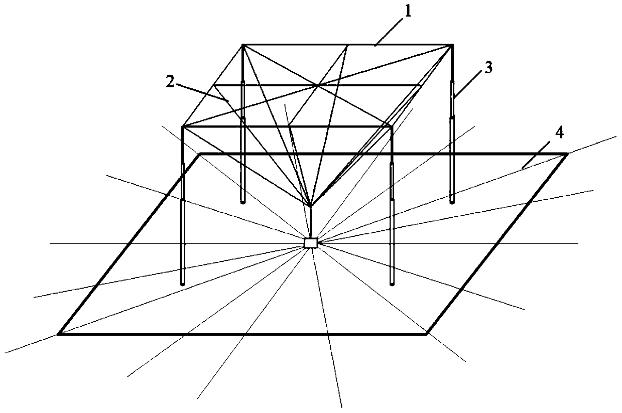
[0025] figure 1 It is a structural schematic diagram of the mobile low-frequency transmitting antenna provided by the embodiment of the present invention, such as figure 1 As shown, the mobile low-frequency transmitting antenna provided by the embodiment of the present invention includes: an antenna body in the shape of an inverted cone, and...


PUM


Abstract

The invention relates to the technical field of antenna equipment and provides a mobile low frequency transmitting antenna which comprises an antenna body in an inverted cone shape. The antenna body comprises a plurality of top wires and a plurality of lead wires. The four top wires are sequentially connected in an end-to-end way to construct the four sides of the top surface of the antenna body.The four lead wires respectively extend downward from the four corners of the top surface and converge to the bottom point to construct the bottom corners of the antenna body. The antenna body of themobile low frequency transmitting antenna is arranged in an inverted cone shape, which is equivalent to increasing the length of the antenna and can effectively reduce the capacitive reactance of theantenna to reduce the antenna voltage and increase the bearing power of the antenna. The conventional tower antenna of several hundred meters can be reduced to several tens of meters and can be more flexible and can be deployed in field positions according to requirements. Although the antenna efficiency is low and the radiation range is limited, the antenna can be used as a supplement to the fixed station and can also make up for the blind area of the fixed station.

Description

technical field [0001] The invention relates to the technical field of antenna equipment, in particular to a mobile low-frequency transmitting antenna. Background technique [0002] Long-wave timing is the use of long-wave (low frequency) for time and frequency transfer and calibration. It is a timing method with stronger coverage than short-wave and higher calibration accuracy. The BPL long-wave timing system undertakes the tasks of time reference maintenance and long-wave timing broadcasting. The center frequency of broadcasting pulse signals is 100kHz, the pulse group repetition period is 60ms, the peak effective power of the transmitter reaches 2MW, and the timing coverage radius reaches 1000km to 2000km. [0003] The long-wave timing system uses high-power fixed broadcasting stations to broadcast timing signals, and basically achieves full coverage in the form of joint coverage of multiple stations in sub-regions. However, there are inevitably a small number of small-s...

Claims


Application Information

Patent Timeline
IPC IPC(8): H01Q1/36H01Q1/48H01Q1/50
CPCH01Q1/36H01Q1/50H01Q1/48
Inventor 赵锦波熊桥坡宋超龙根程磊马思源杨淼罗成
Owner 武汉船舶通信研究所
Why Eureka
Eureka Blog
Learn More