Evaporative cooling system of rail transit traction equipment and rail transit traction equipment

A traction equipment and rail transit technology, applied in the field of rail transit, can solve the problems of increasing the complexity of the heat dissipation system, affecting the life of the insulation layer, and being unable to fully heat up, reducing pipeline layout, ensuring timely maintenance, and reducing volume and weight. Effect

Active Publication Date: 2020-02-11
CSR ZHUZHOU ELECTRIC LOCOMOTIVE RES INST
View PDF3 Cites 1 Cited by
  • Summary
  • Abstract
  • Description
  • Claims
  • Application Information

AI Technical Summary

Problems solved by technology

In the cooling method of the original system, since the transformer needs to be cooled by insulating oil, and the converter is cooled by water, two sets of cooling devices are required, namely, the water cooling device of the converter and the oil cooling device of the transformer, which greatly increases the heat dissipation system. Complexity
In addition, due to the viscosity characteristics of insulating oil, the viscosity is extremely high at low temperature, so the oil pump cannot directly drive the oil circuit to circulate when it is started at low temperature. It needs to be heated first to turn it into a pure liquid state, and then start the pump cycle. For local areas, the oil circuit is widely distributed and cannot be fully heated, so the efficiency is very low
Moreover, inside the transformer, the oil cooling of the original system is to generate oil circulation power through natural convection, and there will be some dead angles. Due to insufficient circulation, the local temperature is high, which seriously affects the life of the insulation layer and leads to failures.

Method used


Image

  • Evaporative cooling system of rail transit traction equipment and rail transit traction equipment
  • Evaporative cooling system of rail transit traction equipment and rail transit traction equipment

Examples


Embodiment Construction

[0027] The present invention will be further described below in conjunction with the accompanying drawings and specific embodiments.

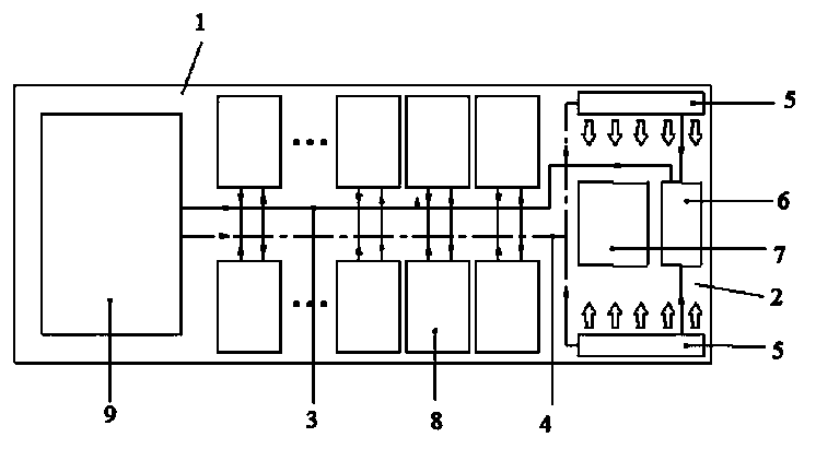
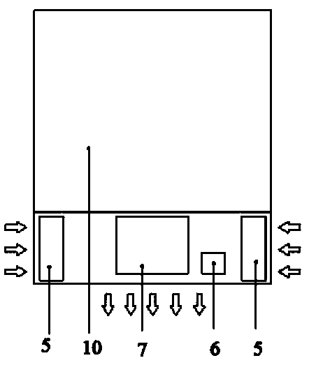
[0028] Such as figure 1 with figure 2 As shown, the evaporative cooling system of rail transit traction equipment in this embodiment includes a water cooling chamber 1, an air cooling chamber 2 and a liquid cooling circuit. , the main water outlet pipe 4 and the heat exchanger, the main water inlet pipe 3 and the main water outlet pipe 4 are located in the middle of the water cooling chamber 1 and arranged along the length direction of the water cooling chamber 1, separating the water cooling chamber 1 into left and right parts for installation of rail transit traction Each power module 8 of the converter in the equipment, in which the main water inlet pipe 3 and the main water outlet pipe 4 are connected to the water cooling plate of each power module 8, so as to evaporate and dissipate heat to each power module 8 (such as spraying the cooli...


PUM


Abstract

The invention discloses an evaporative cooling system of rail transit traction equipment, which comprises a water cooling cavity, an air cooling cavity and a liquid cooling loop, and is characterizedin that a main water inlet pipe and a main water outlet pipe are arranged in the middle of the water cooling cavity and are connected with water cooling plates of power modules in a converter; one endof the main water inlet pipe and one end of the main water outlet pipe are communicated through a transformer heat dissipation assembly, the other end of the main water inlet pipe is connected with adriving part, the other end of the main water outlet pipe is connected with a heat exchanger, and the driving part is connected with the heat exchanger; the heat exchanger is located in the heat dissipation air channel of the air cooling cavity and used for dissipating heat absorbed by the liquid cooling loop into air. The invention further discloses rail transit traction equipment which comprises a converter, a transformer and the evaporative cooling system, all the power modules in the converter are located on the two sides of the water cooling cavity respectively, and the transformer is located at one end of the water cooling cavity. The evaporative cooling system and the rail transit traction equipment have the advantages of being high in integration level, simple and compact in structure, good in heat dissipation effect and the like.

Description

technical field [0001] The invention mainly relates to the technical field of rail traffic, in particular to an evaporative cooling system of rail traffic traction equipment and rail traffic traction equipment. Background technique [0002] With the continuous improvement of rail transit capacity and speed, the demand for reducing weight and volume of traction equipment is increasing. The electrical equipment on the vehicle has heat dissipation requirements. As the demand for weight reduction increases, the power density is also increasing. At the same time, the weight reduction requirements for the cooling equipment itself are also increasing. The equipment on the vehicle includes transformers, converters, switches and other components. Due to the different characteristics of each component, different cooling methods are generally used. For example, the transformer is cooled by circulating silicon oil, the converter is generally water-cooled, and the switching device is nat...

Claims


Application Information

Patent Timeline
Patent Type & Authority Applications(China)
IPC IPC(8): H05K7/20H02M1/00
CPCH02M1/00H05K7/20136H05K7/2029H05K7/20318H05K7/20327
Inventor 姚磊冯钊赞李彦涌何凯支永健李诗怀李奎王春燕马明邓文川郭宗坤田恩曾云峰
Owner CSR ZHUZHOU ELECTRIC LOCOMOTIVE RES INST
Why Eureka
Try Eureka