Roll bending forming method and device for straight edges of to-be-welded pipe

A technology of roll forming and pipe material, which is applied in the field of steel pipe processing, can solve the problems of easy shifting of steel pipe center of gravity, uneven groove, low forming efficiency, etc., achieve stable and reliable manufacturing process, improve process stability, and improve forming quality Effect

Active Publication Date: 2020-02-14
SHANGHAI JIAO TONG UNIV +1
View PDF4 Cites 3 Cited by
  • Summary
  • Abstract
  • Description
  • Claims
  • Application Information

AI Technical Summary

Problems solved by technology

This method has low productivity, high production cost and long production cycle
Another method is to directly cut the straight edge manually, so that there will be uneven groove when cutting the straight edge, and the relative gap of the longitudinal weld is not easy to ensure
In addition, the width of the reserved straight edge is not easy to grasp, and the phenomenon of incomplete elimination of the straight edge is prone to occur, which wastes a lot of pipe materials, increases the cost, and affects the production efficiency
[0003] The existing roll forming method has several problems: (1) continuous roll forming cannot be realized, the forming efficiency is low, and it is difficult to realize industrial promotion; (2) the shape and size of the product cannot meet the radian requirements through one-time forming, and the product Low precision; (3) The process stability is poor, and the center of gravity of the steel pipe is easy to shift during the roll forming process; (4) The versatility is poor, due to the limitation of the mold, only a certain type of pipe can be rolled and formed; (5) The mold input Large, complex structure, increased input costs

Method used


Image

  • Roll bending forming method and device for straight edges of to-be-welded pipe
  • Roll bending forming method and device for straight edges of to-be-welded pipe
  • Roll bending forming method and device for straight edges of to-be-welded pipe

Examples


Embodiment 1

[0047] A continuous roll bending forming method for the straight edge of the edge of the pipe to be welded, comprising the following steps:

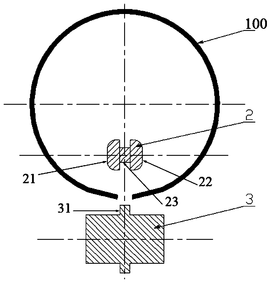
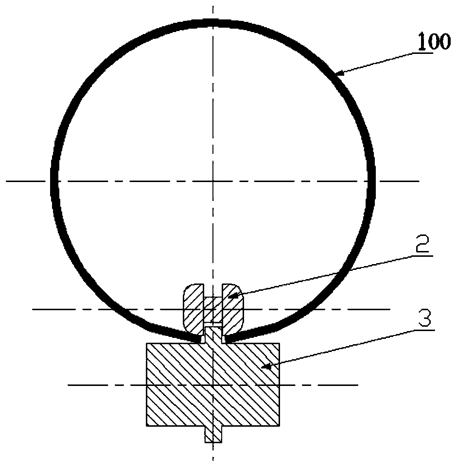
[0048] 1) if figure 1 and figure 2 As shown, after the coiled tube 100 with straight sides is transferred to the importing mold mechanism, the coiled tube 100 is placed on the lower importing die 3 , and the boss 31 on the surface of the lower importing die 3 is inserted between the two straight edges of the coiling tube 100 , the upper import mold 2 is fixed on the inner side of the roll tube 100 by the mold frame. The lower introduction mold 3 rises firstly, abuts against the straight edge of the roll tube 100 from the outer surface of the roll tube 100 and approaches the upper introduction mold 2 . Due to the extruding effect of the forming blocks 21, 22 of the upper leading die and the lower leading die 3, the straight edge of the roll tube 100 is preformed.

[0049] At the same time, the motor drives the lead-in mold 3 to rotate...

Embodiment 2

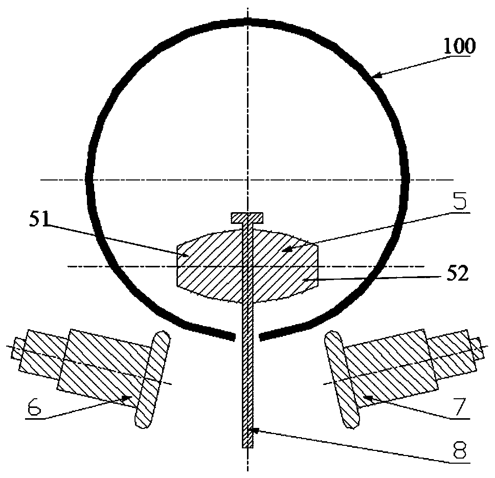
[0057] This embodiment provides a roll-bending method for straight edges of pipes with different diameters to be welded. According to the external dimensions required by pipe products with different diameters, the trajectory of the left-down roll-bending die 6 and the right-down roll-bending die 7 is adjusted so that The lower left roll bending die 6 and the lower right roll bending die 7 move back and forth along the circumferential direction of the coiled pipe edge, thereby realizing the manufacture of pipes to be welded without straight edges of different diameters.


PUM


Abstract

The invention discloses a roll bending forming method for straight edges of a to-be-welded pipe. The roll bending forming method comprises three steps of preforming, roll bending and reshaping; preforming is completed by a leading-in mould; roll bending is completed by a roll bending mould; reshaping is completed by a leading-out mould; and the leading-in mould, the roll bending mould and the leading-out mould are installed on the same equipment through a mould frame, and are driven by a motor, and thereby, integrated roll bending forming of the straight edges of the to-be-welded pipe is realized. The roll bending forming method is high in forming precision and high in consistency and stability and increases production efficiency.

Description

technical field [0001] The invention belongs to the technical field of steel pipe processing, and in particular relates to a straight edge roll bending forming method for the edge of a pipe to be welded. Background technique [0002] Long straight welded pipes are widely used in natural gas, oil and other pipelines. Generally, the production of long straight welded pipes is realized by a plate rolling machine. However, due to the limitation of the plate rolling machine, there must be two straight sides on the edge of the coiled pipe to be welded after the plate rolling is formed. At present, there are mainly two methods for processing the straight edge of the coiled tube. One is to close the remaining straight edges on both sides of the coiled tube and weld the joint to form a flat plate; straight edge. The method has low productivity, high production cost and long production cycle. Another method is to directly cut off the straight edge manually. In this way, there will ...

Claims


Application Information

Patent Timeline
Patent Type & Authority Applications(China)
IPC IPC(8): B21D5/12B21C37/08
CPCB21C37/08B21D5/12
Inventor 曾健王锋华董杰章桢彦
Owner SHANGHAI JIAO TONG UNIV
Why Eureka
Try Eureka