Device and method for producing connecting pipe fitting for plastic compound pipe and application
A technology for connecting pipe fittings and production devices, which is applied in the field of plastic connecting pipe fitting production devices, can solve the problem of inability to produce connecting pipe fittings, etc., and achieves the effects of direct acting force, simple transmission mechanism, and increased product density
- Summary
- Abstract
- Description
- Claims
- Application Information
AI Technical Summary
Problems solved by technology
Method used
Image
Examples
no. 1 example
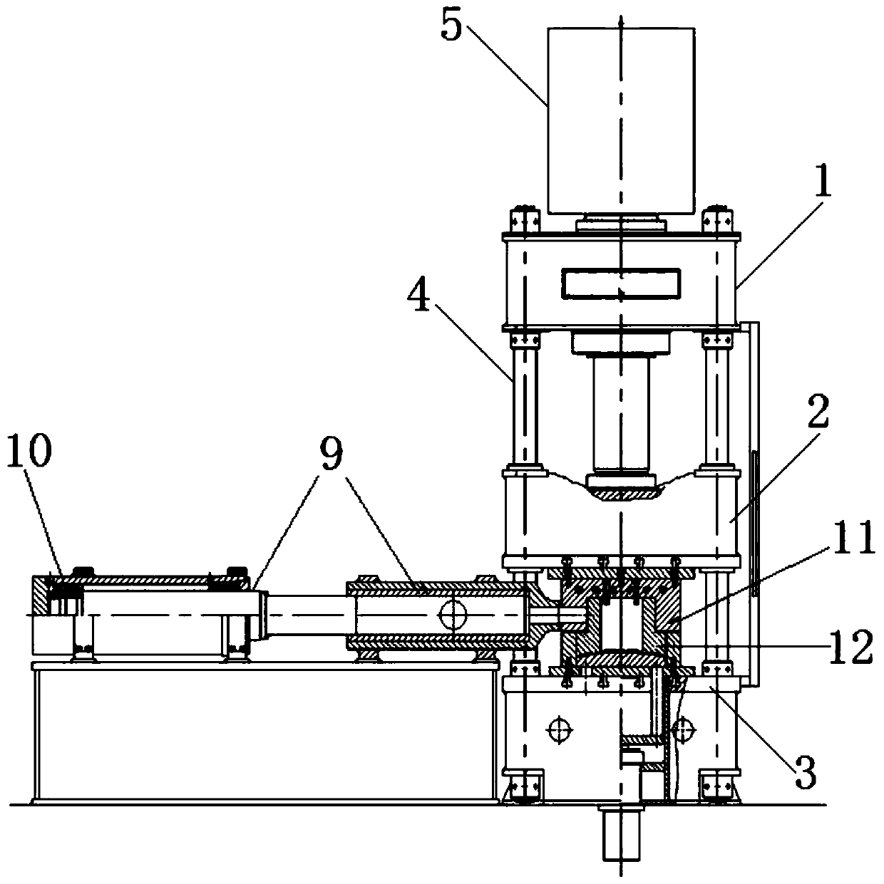
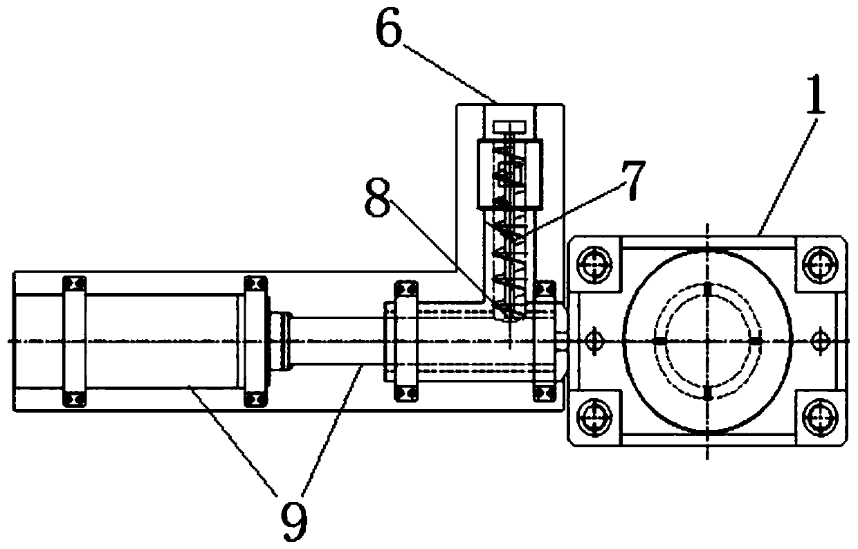
[0039] first embodiment ,refer to figure 1 with 2 , an example of a production device for connecting pipe fittings of plastic composite pipes designed by the present invention, including: a hydroforming device, an extrusion device and a storage device;
[0040] Wherein, the hydraulic forming device includes a vertical hydraulic device and a forming die, and the forming die for forming the connecting pipe fittings is set in the hydraulic device; specifically, the vertical hydraulic device includes: a hydraulic press 1, an upper mold base 2 , the lower mold base 3, the slide rail 4 and the hydraulic machine motor 5, the parts are assembled and distributed in the upper and lower levels, the lower mold base 3 is located at the bottom of the entire hydroforming device, supports the overall device and is fixed on the ground; the slide rail 4 is fixed On the top of the lower die base 3, the slide rail 4 is perpendicular to the lower die base and connects the lower die base with th...
no. 2 example
[0045] second embodiment , there are bolt holes evenly distributed in the circumferential direction at the end face of the cylinder body of the storage cylinder, and the hydraulic motor and the cylinder body of the storage cylinder are sealed and connected by high-strength bolts; one end of the hydraulic rod inside the hydraulic motor is connected to the cylinder body of the storage cylinder The surface is an interference-sealed connection, and extends into the interior of the cylinder body of the storage cylinder, so the cylinder body of the storage cylinder and the hydraulic motor have the same coaxiality and the same relative height; at the same time, in order to avoid vibration during the operation of the motor, the motor and the storage cylinder Cylinder blocks are all located on the top of the accumulator base and are supported by it. During the operation, through the forward rotation and reverse rotation of the motor, the oil inlet and oil return of the liquid medium a...
no. 3 example
[0046] third embodiment ,refer to figure 1 with 2 , the hydraulic press 1 is a four-column hydraulic press, and the slide rails 4 are four cylindrical slide rails 4, which are circumferentially and vertically fixed on the top of the lower mold base 3.
[0047] It should be noted that the technical advantage of this vertically designed hydraulic device is that under the action of the motor of the hydraulic machine, the upper mold base can move up and down in the vertical direction and obtain the required direct force; generally When producing large-diameter, thick-walled, and heavy-weight composite pipe fittings, the hydraulic press designed in this way can provide a clamping force of not less than 30 MPa, which can ensure the upper and lower molds of large-diameter, thick-walled products during the high-pressure injection molding process. The lower two cavity surfaces are always tightly bonded, without any abnormalities affecting production and processing, such as material ...
PUM
| Property | Measurement | Unit |
|---|---|---|
| Outer diameter | aaaaa | aaaaa |
Abstract
Description
Claims
Application Information
 - R&D
- Intellectual Property
- Life Sciences
- Materials
- Tech Scout
- Unparalleled Data Quality
- Higher Quality Content
- 60% Fewer Hallucinations
Browse by: Latest US Patents, China's latest patents, Technical Efficacy Thesaurus, Application Domain, Technology Topic, Popular Technical Reports.
© 2025 PatSnap. All rights reserved.Legal|Privacy policy|Modern Slavery Act Transparency Statement|Sitemap|About US| Contact US: help@patsnap.com


