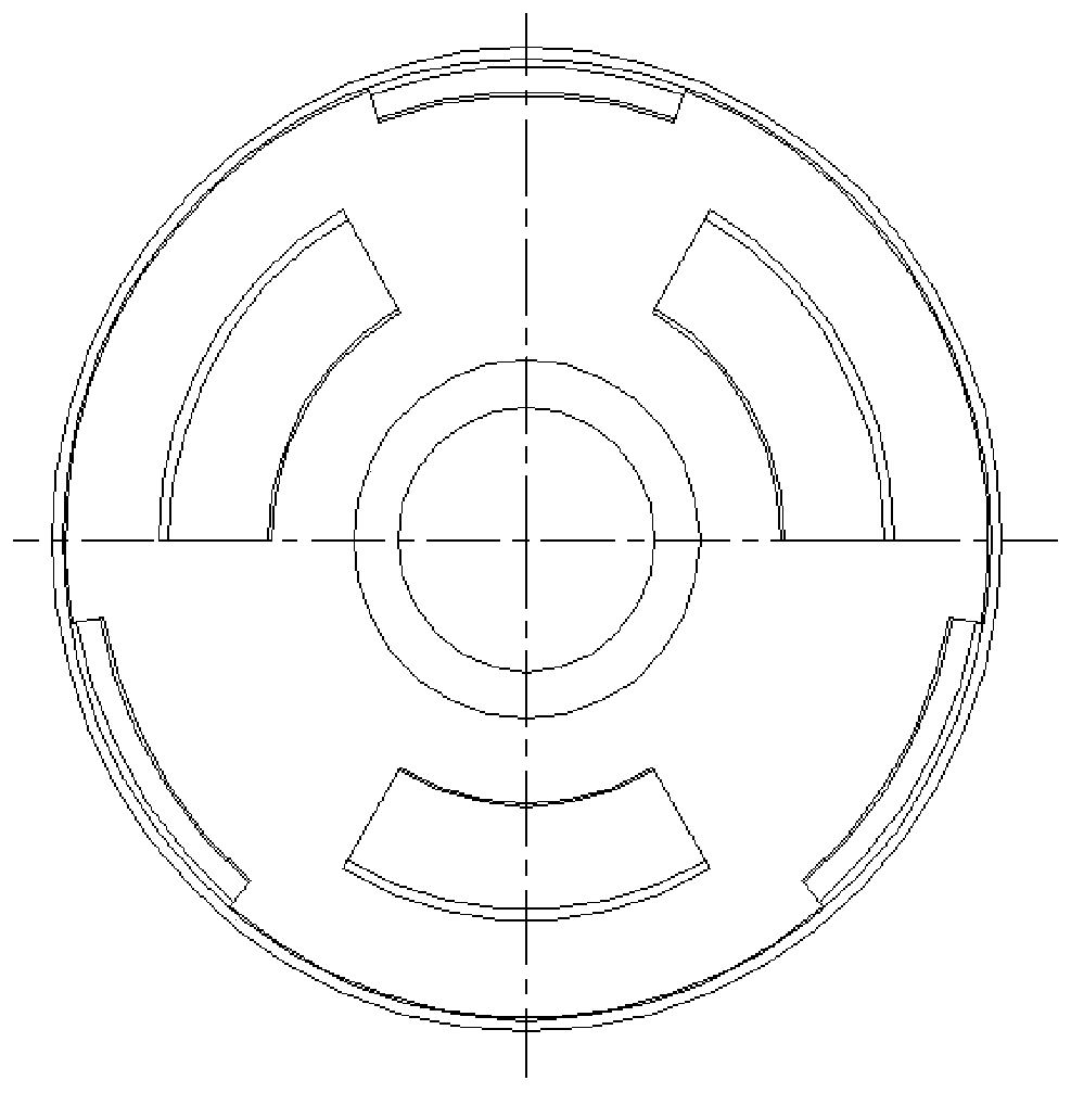
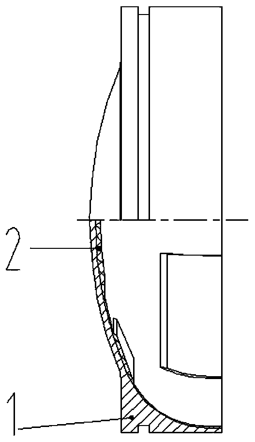
Inner heat insulation layer of front seal head of solid rocket engine and forming method of inner heat insulation layer

A solid rocket and molding method technology, applied in rocket engine devices, machines/engines, coatings, etc., can solve problems such as difficult to achieve thermal insulation layer production, achieve good product quality consistency, reduce negative mass, and high dimensional control accuracy Effect

Active Publication Date: 2020-02-14
SHANGHAI XINLI POWER EQUIP RES INST
View PDF5 Cites 2 Cited by
  • Summary
  • Abstract
  • Description
  • Claims
  • Application Information

AI Technical Summary

Problems solved by technology

The inner heat insulation layer of the front head of the engine is generally molded by pasting the raw film, the thickness of the raw film is limited and the molding process is difficult to meet the needs of the production of ultra-thin and complex inner surface heat insulation layer

Method used


Image

  • Inner heat insulation layer of front seal head of solid rocket engine and forming method of inner heat insulation layer
  • Inner heat insulation layer of front seal head of solid rocket engine and forming method of inner heat insulation layer
  • Inner heat insulation layer of front seal head of solid rocket engine and forming method of inner heat insulation layer

Examples


Embodiment 1

[0046] The front head 1 is made of high-strength steel 30CrMnSiA material, which is machined according to design requirements.

[0047] Follow the steps below to manufacture the inner insulation layer of the front head:

[0048] Step 1: Make an alloy aluminum mold according to the inner surface structure of the inner heat insulation layer, and spray polytetrafluoroethylene on the surface of the mold; the outer surface of the alloy aluminum mold is the same as the inner surface of the heat insulation layer to be formed;

[0049]Step 2: Sand blast the inner wall of the front head to make the inner surface rough, so as to improve the bonding performance between the inner insulation layer and the metal front head, and ensure reliable bonding and no debonding;

[0050] Step 3: preparing a thermal insulation layer in a liquid state;

[0051] Butyl hydroxyl agent: 100 parts, carbon fiber filler 4 parts, boron phenolic resin filler 50 parts, DEHP plasticizer 8 parts, HB crosslinking ...

Embodiment 2

[0058] The front head 1 is made of high-strength steel 30Cr3SiNiMoVA material, which is machined according to design requirements.

[0059] Follow the steps below to manufacture the inner insulation layer of the front head:

[0060] Step 1: Make an alloy aluminum mold according to the inner surface structure of the inner heat insulation layer, and spray polytetrafluoroethylene on the surface of the mold; the outer surface of the alloy aluminum mold is the same as the inner surface of the heat insulation layer to be formed;

[0061] Step 2: Sand blast the inner wall of the front head to make the inner surface rough, so as to improve the bonding performance between the inner insulation layer and the metal front head, and ensure reliable bonding and no debonding;

[0062] Step 3: preparing a thermal insulation layer in a liquid state;

[0063] HTPB base agent: 100 parts, carbon fiber filler 5 parts, boron phenolic resin filler 55 parts, DEHP plasticizer 8 parts, HB crosslinking ...


PUM


Abstract

The invention discloses an inner heat insulation layer structure of a front seal head of a solid rocket engine and a forming method of the inner heat insulation layer structure. A multi-step structureof an inner profile surface of the inner heat insulation layer is realized. The forming method of the inner heat insulation layer comprises the step 1 of manufacturing a mold according to an inner heat insulation layer structure, the step 2 of sandblasting the inner wall surface of the front seal head, the step 3 of preparing a liquid heat insulation layer, the step 4 of pouring the liquid heat insulation layer with the set mass into the front seal head, the step 5 of assembling the mold and the front seal head to a set position to ensure the designed thickness of the heat insulation layer, the step 6 of putting the product into an oven for curing, and the step 7 of taking out the product after the curing time is met, cooling the product to normal temperature, taking out the mold, and shaping and cutting the heat insulation layer to obtain the designed heat insulation layer. The heat insulation layer is high in size control precision, good in quality consistency and simple in process,and the forming method can meet the forming requirements of inner heat insulation layers in various irregular shapes.

Description

technical field [0001] The invention relates to a structure of an inner heat-insulating layer of a front head of a solid rocket motor and a forming method thereof, and belongs to the technical field of the structure of an inner heat-insulation layer of a front head of a solid rocket motor. Background technique [0002] The inner insulation layer is one of the important parts of the thermal protection structure of the solid rocket motor, which plays the role of heat insulation and protection during the working process of the engine, so as to ensure that the metal shell is not ablated by high-temperature gas. As tactical missiles have higher and higher requirements on the performance of solid rocket motors, the charge structure of the motors has become more and more diverse, resulting in an increasingly complex structure of the inner insulation layer. As the negative mass of the engine, the inner heat insulation layer should be designed as thin as possible under the premise of...

Claims


Application Information

Patent Timeline
Patent Type & Authority Applications(China)
IPC IPC(8): F02K9/32C09D161/06C09D7/61C09D7/63
CPCC09D161/06C09D7/61C09D7/63C09D7/70F02K9/32F05D2230/20C08K7/06
Inventor 陈俊毛成立娄永春何快尹胜杰王磊唐亚军纪晓婷左海丽王蓬勃
Owner SHANGHAI XINLI POWER EQUIP RES INST
Why Eureka
Try Eureka